PAGE 84
8.4 HYDRAULIC CYLINDER SEAL REPLACEMENT
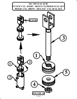
FOR PARTS IDENTIFICATION, REFER TO FIGURE 33 ON THE FOLLOWING PAGE.
1.
After removing the cylinder from the machine, lay it on its side with the ports down and allow the
hydraulic fluid to drain.
2.
After the fluid drains, clamp the cylinder in a vise or similar holding device.
3.
The cylinder head (1) is threaded into the body (2) of the cylinder. There are pin holes in the top of
the head for a pin wrench.
4.
To remove the head, remove the set screw from the head and place a pin wrench in the pin hole on
the head and rotate the head counterclockwise to unscrew from the body.
5.
After the head has been unscrewed, anchor the cylinder body (2) solidly and hook a come-a-long to
the cylinder clevis and pull the head (1) and cylinder shaft (3) out of the tube.
6.
Remove the locking nut (4) from the cylinder shaft (3) and slide the piston (5) and head (1) off
of the shaft and remove all of the seals.
7.
Clean all of the parts and inspect the inside of the tube, the piston, the shaft and the inside of the
head for scoring or nicks.
8.
Install the new seals and lubricate them before re-assembling the parts.
9.
Place the head and piston on the shaft and torque the locking nut on the shaft to 100 foot pounds.
To prevent the nut from working loose after the cylinder has been reassembled, rivet the threads
on the end of the ram with a chisel or punch.
10.
Stand the cylinder tube upright in a vise and place the shaft assembly on the tube.
11.
Tap the head and piston down into the tube with a brass or plastic hammer.
12. Screw the head back into the tube with the pin wrench and reinstall set screw.
For the SHEAR/NOTCH station of the machine, power the machine and place a thick piece of steel on
the far left side of the bar shear furthest away from the pivot pin and clamp it down with the hold down
device. Attempting to shear the piece should stall the machine. Watch the pressure gauge for a reading.
The system pressure of this station is 3,500 PSI (241 BAR) plus or minus 50 PSI (3.5 BAR). If pressure is
out of this range, call your local dealer or the factory.
For the PUNCH/TOOL station of the machine the pressure setting is 3,500 PSI (241 BAR) plus or minus
50 PSI (3.5 BAR). To set the pressure, remove the die holder, punch and punch retaining nut. Place a
substantial block of steel, at least four inches square and eight and one half inches tall, under the punch
ram.
Place the RUN/JOG switch in the JOG position and the selector switch in the TOOL position. Power the
machine and jog the ram down to the block and stall the machine, reading the gauge at the same time.

