PAGE 26
15.
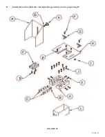
Raise the punch retaining nut (C) and turn it on to the punch ram. (The die holder may have to be
moved slightly to align the punch retaining nut to the punch ram.)
16.
If you are using a keyed punch, manually rotate the punch until the key seats in the ram, before
tightening the punch retaining nut.
17.
Use a wrench to tighten the punch retaining nut (C). Make sure that there is equal clearance on all
sides of the punch in the die.
18.
Re-tighten the bolts (B) in the die holder.
19.
Check to be sure of proper alignment. Realign, if necessary.
20.
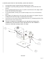
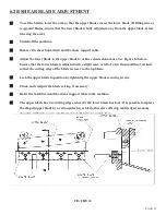
Return the stripper to the FORWARD position. (For stripper adjustment procedures, SEE
FIGURE 9 ON PAGE 27.)
21.
Place the disconnect switch in the ON position and the selector switch in the START position.
Power the machine by pressing the green START button.
22.
Place the selector switch in the SHEAR position. Jog the machine several times with the foot
switch, without letting the punch come out of the die, to be sure that the alignment is correct.
23.
Place the selector switch in the PUNCH position.
24.
Oil the punch and die every five to ten holes.
B. KEYED PUNCHES:
This machine is equipped with a 1/4 inch (6.3mm) keyed punch ram. When punching holes other than
rounds, we recommend using keyed punches. All Scotchman shaped punches are supplied with the
keyway as standard equipment.
NOTE: If you do not use keyed punches, it may be helpful to hold the body of the punch with a
wrench while tightening the punch retaining nut. This will help to keep the punch from rotating
with the nut as it is being tightened.
C.
CHECK ALL PUNCHING TOOLS FOR TIGHTNESS.
The punch and die alignment should be checked intermittently during punching operations. To do this,
bring the punch down so that it enters the die. Turn the machine off. Check and tighten the punch
retaining nut, the set screws holding the die and die insert and the bolts holding the die and the die
holder. Check for equal clearance between the punch and die. Place the selector switch in the START
position and the run/jog switch in the JOG position and power the machine. Place the selector switch in
the SHEAR position and jog the machine several times, to be sure of proper alignment. Place the selector
switch in the PUNCH position and the run/jog switch in the RUN position.
Summary of Contents for FI-8510-20M
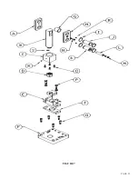
Page 10: ...PAGE 9 FIGURE 1...
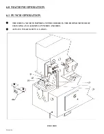
Page 12: ...PAGE 11 FIGURE 2...
Page 24: ...PAGE 21 FIGURE 6...
Page 26: ...PAGE 23 FIGURE 7...
Page 38: ...PAGE 35 FIGURE 15...
Page 40: ...PAGE 37 FIGURE 16...
Page 42: ...PAGE 39 FIGURE 17...
Page 48: ...PAGE 45 FIGURE 20...
Page 50: ...PAGE 47 FIGURE 21...
Page 52: ...PAGE 49 FIGURE 22...
Page 56: ...PAGE 53 FIGURE 24...
Page 58: ...PAGE 55 FIGURE 25...
Page 62: ...PAGE 59 FIGURE 26...
Page 64: ...PAGE 61 FIGURE 27...
Page 68: ...PAGE 65 FIGURE 29...
Page 74: ...PAGE 71 FIGURE 30...
Page 76: ...PAGE 73 FIGURE 31...
Page 80: ...PAGE 77 FIGURE 33...
Page 82: ...PAGE 79 FIGURE 34...
Page 84: ...PAGE 81 FIGURE 35...
Page 88: ...PAGE 85 FIGURE 37...
Page 90: ...PAGE 87 FIGURE 38...
Page 92: ...PAGE 89 FIGURE 39...
Page 94: ...PAGE 91 FIGURE 40...
Page 96: ...PAGE 93 FIGURE 41...
Page 100: ...PAGE 97 FIGURE 43 SERIAL S 4481 UP...


