PAGE 27
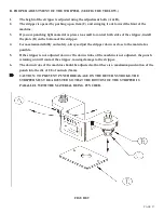
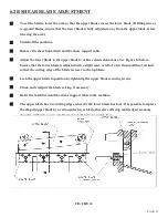
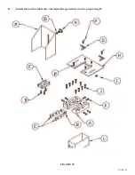
D. PROPER ADJUSTMENT OF THE STRIPPER. (SEE FIGURE 9 BELOW.)
1.
The height of the stripper is adjusted using the adjustment bolts (A & B).
2.
The stripper is opened by pushing up on item (C) and swinging it out toward the front of the
machine.
3.
If you are punching light material or pieces too small to contact both sides of the stripper, install
the plate (D) on the bottom of the stripper.
4.
For maximum visibility and safety, always adjust the stripper down as close to the material as
possible.
5.
If the stripper is not adjusted down or the down stroke of the machine is not adjusted, the punch
retaining nut will contact the stripper, causing damage to the stripper.
6.
The down stroke of the machine should be adjusted so that there is a maximum penetration of the
punch into the die of 1/8 of an inch (3mm).
CAUTION: TO PREVENT PUNCH BREAKAGE ON THE RETURN STROKE, THE
STRIPPER MUST BE ADJUSTED SO THAT THE BOTTOM OF THE STRIPPER IS
PARALLEL WITH THE MATERIAL BEING PUNCHED.
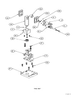
FIGURE 9
Summary of Contents for FI-8510-20M
Page 10: ...PAGE 9 FIGURE 1...
Page 12: ...PAGE 11 FIGURE 2...
Page 24: ...PAGE 21 FIGURE 6...
Page 26: ...PAGE 23 FIGURE 7...
Page 38: ...PAGE 35 FIGURE 15...
Page 40: ...PAGE 37 FIGURE 16...
Page 42: ...PAGE 39 FIGURE 17...
Page 48: ...PAGE 45 FIGURE 20...
Page 50: ...PAGE 47 FIGURE 21...
Page 52: ...PAGE 49 FIGURE 22...
Page 56: ...PAGE 53 FIGURE 24...
Page 58: ...PAGE 55 FIGURE 25...
Page 62: ...PAGE 59 FIGURE 26...
Page 64: ...PAGE 61 FIGURE 27...
Page 68: ...PAGE 65 FIGURE 29...
Page 74: ...PAGE 71 FIGURE 30...
Page 76: ...PAGE 73 FIGURE 31...
Page 80: ...PAGE 77 FIGURE 33...
Page 82: ...PAGE 79 FIGURE 34...
Page 84: ...PAGE 81 FIGURE 35...
Page 88: ...PAGE 85 FIGURE 37...
Page 90: ...PAGE 87 FIGURE 38...
Page 92: ...PAGE 89 FIGURE 39...
Page 94: ...PAGE 91 FIGURE 40...
Page 96: ...PAGE 93 FIGURE 41...
Page 100: ...PAGE 97 FIGURE 43 SERIAL S 4481 UP...


