background image

8.0 MAIN FRAME ASSEMBLY

ITEM                       PART #                          DESCRIPTION

1                            2059000064                         Working plate

2                            2050000322                         Roker support

3                            2050000322                         Roker

4                            2040000072                         Rocker rotation shaft

5                            TD12500012                       M-12 washer

6                            TD91212025                       DIN 912 M-12 x 25 PIN

7                            2059007522                         7.5 HP III phase motor

8                            2169000142                         Motor pulley J16

9                            TD93110050                       DIN 931 M-10 x 50 PIN

10                          2050000092                         Rectified Ø100 shaft

11                          2040000172                         4206 bearing

12                                                                       Separators

13                          2169000132                         Rocker pulley J16

14                          205DW35032                      Ø500 blade

15                          2050000032                         Blade washer

16                          2040000232                         Blade nut

17                          1283                                     Poly Belt For GAA-500 7.5hp Ref# 1283

17A                       C2050000012                      J12 Poly V-Belt - Older 5.5hp saws use this belt

18                          2059000024                         Turret

19                                                                       Left turret plate

20                                                                       Right turret plate

21                          TD69120616                       DIN 6912 M-6 x 16 PIN

22                          2040000062                         Ø45 Aluminum rod

23                          B000001070                        M-10 x 70 Pull

24                          1677                                     Ø45 Pneumatic hold-down clamp

25                          2350000131                         Nylon cleat

26                          2090000191                         Ø36 Horizontal rod

27                          B000006x40                        M-10 x 40 Pull

28                          C2070000295                      Ø36 x 225 Pneumatic clamp

29                          2050000172                         GAA Clamp Block

30                                                                       Blade groove GAA-500

31                                                                       DIN 7991 M-6 PIN

Page 22

5167

Summary of Contents for GAA-500-90 CNC DT20

Page 1: ...PRINTED OCTOBER 2020 MODEL GAA 500 90 CNC DT20 AUTO UPCUT COLD SAW WWW SCOTCHMAN COM...

Page 2: ...akdowns 6 4 Manufacturer recommendations 7 0 DRAWINGS AND SCHEMATICS 8 0 MAIN FRAME ASSEMBLY 9 0 SHUTTLE FEED SYSTEM 10 OPTIONAL CHIP COLLECTOR WIRE LOCATIONS 1 INTRODUCTION This instruction manual ha...

Page 3: ...of date of purchase replace F O B the factory or refund the purchase price for any goods which are defective in materials or workmanship and at the seller s option returns the defective goods freight...

Page 4: ...MACHINING A 70 X 50 PROFILE 108 Db A Leq ATTENTION When working with the machine use individual hearing protection equipment Characteristics Dimension Three phase motor 4 HP 230 400 V Motor speed 3 0...

Page 5: ...iately The machine must be installed on a firm and level surface in order to thus reduce vibrations during operation and so that the machine operates within the parameters established by the manufactu...

Page 6: ...oosen the blade nut ATTENTION Assure that the blade is adapted for this machine Diameter of the axis 50mm DANGER After changing the blade put the sheet metal front back on 4 4 CUTTING COOLANT In order...

Page 7: ...ailure to comply with the aforementioned 5 2 FUNCTION OF THE OPERATING MECHANISMS 1 Blue push button To re arm machine 2 Operating mode selector MANUAL AUTOMATIC 3 Green push button Automatic cycle st...

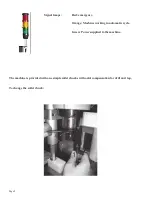
Page 8: ...ps Red emergency Orange Machine working in automatic cycle Green Power supplied to the machine The machine is provided with one simple collet chucks with axial compensation for drill and tap To change...

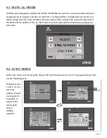
Page 9: ...e feed not be used as this would greatly reduce the duration of the blade and the quality of the cut The feeder can also be operated for maintenance purposes in this mode 5 4 AUTO MODE In the auto mod...

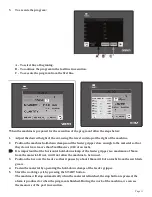
Page 10: ...TO CREATE TO MODIFY AND TO EXECUTE A PROGRAM OF WORK 1 Select the program of work 2 Select the part list and the number of pieces If you don t program code of piece or number of pieces the program is...

Page 11: ...than 5 millimeters 2 10 of an inch It is important that the horizontal hold down clamp of the feeder gripper is a maximum of 5mm from the material If not it will not allow the machine to be turned 3 P...

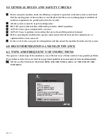
Page 12: ...ALWAYS wear regulation work clothes that are not loose fitting and are fastened Before operating the machine the operator must ensure that all tools used for maintenance or adjustment have been remove...

Page 13: ...Page 13 ATTENTION Every eighty hours LUBRICATE 2 strokes KLUBER ISOFLEX NBU 15 In the SETUP menu we can modify the parameters of the machine The password 7890 may be used by qualified personnel only...

Page 14: ...se Check the condition of the transformer THE FEEDER DOES NOT WORK CORRECTLY Check the status of all end of travel stops and the positioning of same Check the condition of SERVO DRIVE Check the condit...

Page 15: ...he cable has the appropriate cross section for the power of the machine Whenever any part has to be replaced use an original replacement part and endeavor to use the oil recommended by the manufacture...

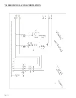
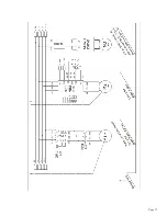
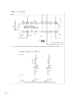
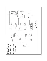
Page 16: ...Page 16 7 0 DRAWINGS AND SCHEMATICS...

Page 17: ...Page 17...

Page 18: ...Page 18...

Page 19: ...Page 19...

Page 20: ...Page 20...

Page 21: ...Page 21...

Page 22: ...ker pulley J16 14 205DW35032 500 blade 15 2050000032 Blade washer 16 2040000232 Blade nut 17 1283 Poly Belt For GAA 500 7 5hp Ref 1283 17A C2050000012 J12 Poly V Belt Older 5 5hp saws use this belt 18...

Page 23: ...29 LEFT SIDE CLAMP RIGHT SIDE CLAMP 17 Page 23...

Page 24: ...13 25 x 2250 PVC Roller 14 Back Feeder Support 15 32 x 300 PVC Roller 16 Back Roller Support 17 Screw Separating Tip 18 CR0003204RS 3204 2RS Bearing 19 Screw Separating Tip 20 CTP00FR2010 M 20 x 1 Pr...

Page 25: ...ever 43 CN0000C4010 40 x 10 D E Compact Cylinder 44 CTD91206060 DIN 912 M 6 45 x 60 Screw 45 P2359001734 Horizontal Nylon Cleat 46 Plate Support 47 Material Plate 48 CTD91208020 DIN 912 M 8 x 20 Screw...

Page 26: ...3 Scotchman Inds PART NO 0 02 5mm 00 01 25mm 000 005 125mm Fractions 1 32 7mm Angles 1 DATE DWN BY SCALE PART NAME CHK BY TOLERANCE UNLESS SPECIFIED Chip Collector GAA 500 GAA 600 Saws BROWN BLUE BROW...

Reviews: