background image

Page 32

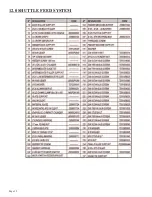
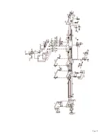
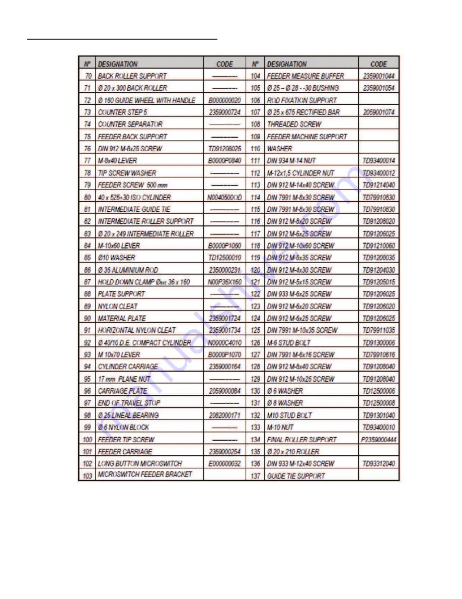
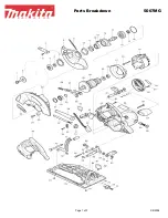
12.0 SHUTTLE FEED SYSTEM

Summary of Contents for GAA-500-90 NF

Page 1: ...PRINTED OCTOBER 2020 Page 1 MODEL GAA 500 90 NF AUTO UPCUT COLD SAW WWW SCOTCHMAN COM...

Page 2: ...9 0 PNEUMATIC COMPONENTS 10 VALVE BANK 11 MAIN FRAME ASSEMBLY 12 SHUTTLE FEED SYSTEM 13 OPTIONAL CHIP COLLECTOR WIRE LOCATIONS 1 0 INTRODUCTION This instruction manual has been made in compliance with...

Page 3: ...e price for any goods which are defective in materials or workmanship and at the seller s option returns the defective goods freight and delivery prepaid to the seller which shall be the buyer s sole...

Page 4: ...that appears in the last chapter of the parts exploded views 2 2 TECHNICAL DATA Characteristics Dimension Three phase motor 7 1 2 HP 220 460 V Motor speed 3 000 RPM Interior of blade 50mm 2 Maximum o...

Page 5: ...LOAD 68 Db A Leq MACHINING A 70 X 50 PROFILE 108 Db A Leq ATTENTION When working with the machine use individual hearing protection equipment 2 5 BASE CABINET Power supply Motor power Total consumpti...

Page 6: ...alled on a firm and level surface in order to thus reduce vibrations during operation and so that the machine operates within the parameters established by the manufacturer 4 2 POWER SUPPLY CONNECTION...

Page 7: ...e up against the pin 2 and lock the blade in place The teeth of the blade rotate away from the operator when the operator is standing in front of the machine CAUTION Make sure that the blade is instal...

Page 8: ...NG MECHANISMS Indicator lights Green Power supplied to the machine Red Emergency Yellow Protective shield lifted Saw blade on off On green colored symbol I Off red O Emergency button with interlock It...

Page 9: ...Page 9...

Page 10: ...ndicator light G This is the E Stop H This is the shuttle feed rate adjustment I This is the blade feed adjustment J This is the motor start and stop switch K There are two K buttons These buttons are...

Page 11: ...Page 11 FIGURE 1...

Page 12: ...stops the machine completely thereby keeping the material tight in the hold down clamps H Feeder speed regulator I Blade raise advance J Saw blade on off On green colored symbol I Off red O K Saw blad...

Page 13: ...Page 13 THIS PAGE LEFT BLANK INTENTIONALLY...

Page 14: ...d place the machine in the Manual Mode Set your part length with the length hand wheel on the left side of the saw Figure 2 Place the shuttle selector switch in the 1 or 2 hitch position Start the aut...

Page 15: ...Page 15 FIGURE 2 FIGURE 3...

Page 16: ...Page 16 FIGURE 5...

Page 17: ...Page 17 FIGURE 6...

Page 18: ...ve been removed In the event of a fire use powder extinguishers and disconnect the machine from the electric system 6 0 RECOMMENDATIONS AND MAINTENANCE 6 1 TYPE FREQUENCY OF INSPECTIONS The operator s...

Page 19: ...ops and the positioning of the same Check the condition of all electrovalbves Check the condition of the automata feeder box and the voltage on the line itself 110 VAC Check the pressure at the regula...

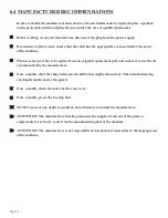
Page 20: ...se an original replacement part and endeavor to use the oil recommended by the manufacturer Once a month all of the chips in the saw should be thoroughly cleaned out This includes blowing out chips fr...

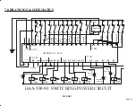
Page 21: ...40 14 1R 22 COUNTER 1 1R 2 0 EMERGENCY SHIELD UP EMERGENCY INDICATOR RED GREEN AUTO ON INDICATOR SHIELD UP INDICATOR YELLOW LOWER SHIELD 63 62 RAISE SHIELD BLADE MOTOR FEEDER JAWS BLADE CLAMPS VOLTAGE...

Page 22: ...Page 22 POWER CIRCUIT FIGURE 8...

Page 23: ...Page 23 FIGURE 9...

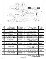
Page 24: ...2050000142 24 45 PNEUMATIC HOLD DOWN CLAMP TD12500012 21 DIN 6912 M 6 X 16 PIN TD69120616 45 ALUMINUM ROD 2040000062 B000001070 1677 2350000131 10 RECTIFIED 100 SHAFT 2050000092 26 36 HORIZONTAL ROD...

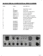
Page 25: ...1 E000000S70 E000000067 DESCRIPTION Digital Pulse Counter Feeder start Lift protective shield selector Protective shield lifted Emergency indicator Power supplied to the machine Emergency button with...

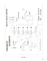
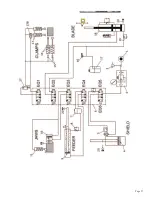
Page 26: ...KLHOG 8 ORZ UHJXODWLRQ OHFWURYDOYHV PDQLIROG 2OHRQHXPDWLF FRQYHUWHU ORZ UHJXODWLRQ RLO OLQGHU RLO IURQW O RPSDFW GRXEOH DFW 9HUWLFDO FODPS 4XLFN H KDXVW YDOYH ROGGRZQ ODPS 00 RUL RQWDO FODPSV DOO YDOY...

Page 27: ...Page 27...

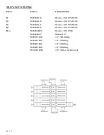
Page 28: ...4 Electrov 5 2 1 8 MONO Q3 N000000A34 Electrov 5 2 1 8 MONO Q4 N000000A34 Electrov 5 2 1 8 MONO Q5 6 N00000AB34 Electrov 5 2 1 8 BI N000000S14 Silencer 1 4 N000CC1408 1 4 8 L fitting N000RC1804 1 8 4...

Page 29: ...Page 29 THIS PAGE LEFT BLANK INTENTIONALLY...

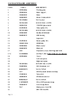
Page 30: ...ker pulley J16 14 205DW35032 500 blade 15 2050000032 Blade washer 16 2040000232 Blade nut 17 1283 Poly Belt For GAA 500 7 5hp Ref 1283 17A C2050000012 J12 Poly V Belt Older 5 5hp saws use this belt 18...

Page 31: ......

Page 32: ...Page 32 12 0 SHUTTLE FEED SYSTEM...

Page 33: ...Page 33...

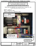
Page 34: ...3 Scotchman Inds PART NO 0 02 5mm 00 01 25mm 000 005 125mm Fractions 1 32 7mm Angles 1 DATE DWN BY SCALE PART NAME CHK BY TOLERANCE UNLESS SPECIFIED Chip Collector GAA 500 GAA 600 Saws BROWN BLUE BROW...

Reviews: