Page 6
3.0 INDICATIONS REGARDING TRANSPORT/STORAGE
The machine is delivered on a pallet in order to be transported by forklift.
Store in the vertical position.
Do not stack.
If the machine remains stored for a long period of time, periodically lubricate it.
Do not expose to the elements.
The packaging is made of properly designed and sized wood and it is also supplied wrapped in plastic.
CAUTION: Do not improperly dispose of the packaging. Send this material to be recycled or
disposed of in accordance with all legislation in force.
4.0 INSTRUCTIONS FOR ANCHORING & SERVICE START-UP
4.1 ANCHORING INSTRUCTIONS
Ensure that the machine has not suffered any damage during transport by making an initial visual
inspection. If damage is observed, advise the manufacturer immediately.
The machine must be installed on a firm and level surface in order to thus reduce vibrations during
operation and so that the machine operates within the parameters established by the manufacturer.
4.2 POWER SUPPLY CONNECTION
Verify that the power supply voltage indicated on the specifications plate of the machine. Connect the
cable to the power supply, using a plug that is appropriate for the characteristics of the same, thereby
respecting the color codes.
Once the machine is connected, verify that the motor rotation agrees with the direction of the saw blade
teeth (rotation to the right). If the motor rotation was not correct, change the two phases of the motor.
Then, check the rotation again. The blade teeth should rotate to the back of the machine as it comes up
through the base.
The pneumatic connection must be made to the supply system, using a tube that is appropriate for the
spigot of the machine. Adjust the pressure at the filtering group.
ATTENTION! The pneumatic working pressure must be between 90 to 105 psi.
Summary of Contents for GAA-500-90 NF
Page 1: ...PRINTED OCTOBER 2020 Page 1 MODEL GAA 500 90 NF AUTO UPCUT COLD SAW WWW SCOTCHMAN COM...
Page 9: ...Page 9...
Page 11: ...Page 11 FIGURE 1...
Page 13: ...Page 13 THIS PAGE LEFT BLANK INTENTIONALLY...
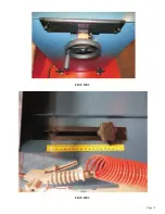
Page 15: ...Page 15 FIGURE 2 FIGURE 3...
Page 16: ...Page 16 FIGURE 5...
Page 17: ...Page 17 FIGURE 6...
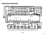
Page 22: ...Page 22 POWER CIRCUIT FIGURE 8...
Page 23: ...Page 23 FIGURE 9...
Page 27: ...Page 27...
Page 29: ...Page 29 THIS PAGE LEFT BLANK INTENTIONALLY...
Page 31: ......
Page 32: ...Page 32 12 0 SHUTTLE FEED SYSTEM...
Page 33: ...Page 33...


