Page 20
5.3 SCHEDULED MAINTENANCE
A program of scheduled maintenance should be set up and documented according to your application
and the frequency you use this machine. The following is a list of important items that should be
included in a scheduled maintenance program:
1.
EVERY 500 HOURS OR 6 MONTHS:
A.
Check the tolerance between the punch ram and the punch ram bushing.
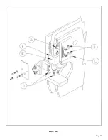
To check the tolerances, remove the punch ram and the bushing from the machine. For parts
identification, SEE FIGURE 7 ON THE FOLLOWING PAGE.
1.
To remove the punch ram and bushing, cycle the machine until the upper punch pin (A) aligns with
the access hole in the frame.
2.
Remove the two mounting bolts (B) from the stroke control mounting plate (C) and remove the
stroke control assembly.
3.
Remove the die holder and block up the punch ram.
4.
Remove the snap ring retainers from the upper punch pin and remove the four mounting bolts (D)
and the grease bolt (E) from the punch ram bushing (F).
5.
Remove the punch ram and the bushing. Care should be taken when removing these parts;
THEY ARE HEAVY.
6.
Clean all grease and dirt off both parts and check the clearance between the outside diameter of the
punch ram and the inside diameter of the punch ram bushing. If the clearance between the two
parts is five thousandths (.005) or more, replace both parts. Reassemble parts in reverse order.
B.
Check the condition of the cutting blades on the bar shear, angle shear and any other component
tool.
C.
Check the condition of the bushing in the upper arm and shear arm. This can be done by visually
watching the arms for vertical movement while the machine is in operation.
If vertical movement is noted, block or support the arms with a lifting device and remove the pin
and check the clearance. If the clearance between the pin and the bushing exceeds twelve (.012)
thousandths (.3mm), replace the bushing. Since the 6509-24M can be used for a wide variety of
applications with many optional tools, these may not be all of the items that you need to include in a
scheduled maintenance program.
If you have questions about other applications, contact your local dealer or the factory.
Summary of Contents for IRONWORKER 6509-24M
Page 1: ...Page 1 MODEL 6509 24M IRONWORKER PRINTED MARCH 2005...
Page 9: ...Page 9 FIGURE 1...
Page 17: ...Page 17 FIGURE 5...
Page 19: ...Page 19 FIGURE 6...
Page 21: ...Page 21 FIGURE 7...
Page 31: ...Page 31 FIGURE 11...
Page 33: ...Page 33 FIGURE 12...
Page 35: ...Page 35 FIGURE 13...
Page 39: ...Page 39 FIGURE 15...
Page 41: ...Page 41 FIGURE 16...
Page 47: ...Page 47 FIGURE 20...
Page 51: ...Page 51 FIGURE 22...
Page 55: ...Page 55 FIGURE 25...
Page 59: ...Page 59 FIGURE 27...
Page 69: ...Page 69 FIGURE 30...
Page 71: ...Page 71 FIGURE 31...
Page 75: ...Page 75 FIGURE 34...
Page 79: ...Page 79 FIGURE 37...
Page 81: ...Page 81 FIGURE 38...
Page 85: ...Page 85 FIGURE 40 Serial s 5035FF1094 to 7124FF103...


