Page 23
A.
ALIGNMENT AND REMOVAL OF PUNCHES AND DIES:
WARNING: Failure to properly align punches and dies can cause serious bodily injury to personnel
and/or damage to equipment. Please read carefully and understand the following method. It will also
be helpful to refer to the safety tape provided for a visual reference. If you did not receive a safety
tape, please contact your dealer or the factory.
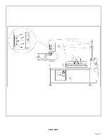
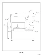
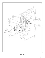
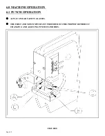
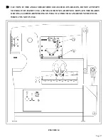
For parts identification, REFER TO FIGURE 8 ON THE PRECEDING PAGE.
MOVE ALL TOOLING TO THE BACK OF THE TOOL TABLE AND CRANK THE BAR
SHEAR HOLD-DOWN TO THE DOWN POSITION WHEN PUNCHING.
FAILURE TO MOVE THE ANGLE SHEAR, CHANNEL SHEAR, BRAKES ETC., OUT FROM
UNDER THE UPPER ARM CAN RESULT IN POSSIBLE DANGER TO OTHER PERSONNEL
AND DAMAGE TO THE TOOLS.
1.
With the machine in the PUNCH position, turn the machine’s electrical power off at the disconnect
switch.
2.
Release the stripper and swing it to the side, out of the way of the punch ram and the punch
retaining nut (A).
3.
Loosen the die holder bolts (B).
4.
Loosen and remove the punch retaining nut (A) and set the punch retaining nut and punch aside.
5.
Loosen the two set screws (D) holding the die insert (C). Remove the die insert and loosen the set
screw holding the die on, remove it and set it aside.
CAUTION: IF YOU ARE USING THE OFFSET DIE HOLDER FOR FLANGED PUNCHING,
PLEASE SEE SPECIAL INSTRUCTIONS IN SECTION 7.9B.
6.
Place the disconnect switch in the ON position and the selector switch in the START position. Power
the machine by pressing the green START button.
7.
Check to make sure that there are no objects (such as tools) on or under any of the moving parts.
8.
Place the selector switch in the SHEAR position and allow the ram to extend.
9.
Turn the machine's power off.
10. Clean the die insert cavity of any foreign material.
11. Select the proper punch and die. Make sure that there is proper clearance between the punch and
die. For recommended clearances, SEE SECTION 6.1, PARAGRAPH G.
12. Clean both the punch and the die.
13. Insert the proper die in the die insert (C). (If the die has a flat spot in it, align this with the set screw
in the die insert.) Tighten the set screw firmly with an allen wrench.
14. Insert the punch into the punch retaining nut (A), making sure that it seats properly. Place the
punch retaining nut assembly on the die insert, with the punch inserted in the die.
Summary of Contents for IRONWORKER 6509-24M
Page 1: ...Page 1 MODEL 6509 24M IRONWORKER PRINTED MARCH 2005...
Page 9: ...Page 9 FIGURE 1...
Page 17: ...Page 17 FIGURE 5...
Page 19: ...Page 19 FIGURE 6...
Page 21: ...Page 21 FIGURE 7...
Page 31: ...Page 31 FIGURE 11...
Page 33: ...Page 33 FIGURE 12...
Page 35: ...Page 35 FIGURE 13...
Page 39: ...Page 39 FIGURE 15...
Page 41: ...Page 41 FIGURE 16...
Page 47: ...Page 47 FIGURE 20...
Page 51: ...Page 51 FIGURE 22...
Page 55: ...Page 55 FIGURE 25...
Page 59: ...Page 59 FIGURE 27...
Page 69: ...Page 69 FIGURE 30...
Page 71: ...Page 71 FIGURE 31...
Page 75: ...Page 75 FIGURE 34...
Page 79: ...Page 79 FIGURE 37...
Page 81: ...Page 81 FIGURE 38...
Page 85: ...Page 85 FIGURE 40 Serial s 5035FF1094 to 7124FF103...


