Page 25
NOTE: WHEN PUNCHING LARGE DIAMETER HOLES, OR IN CASES OF HIGH PUNCH
SHOCK, IT WILL HELP IF THE STROKE OF THE MACHINE IS ADJUSTED SO THAT THE
PUNCH STOPS JUST ABOVE THE PLANE OF THE DIE, APPROXIMATELY FIFTEEN
THOUSANDTHS OF AN INCH (.3MM).
C.
DO NOT PUNCH ANYTHING THICKER THAN THE PUNCH DIAMETER.
This "rule of thumb" can be extended, but the punch supplier or Scotchman should be consulted first,
(i.e. do not punch plate thicker than 1/2 inch with a 1/2 inch diameter punch). This rule of thumb applies
to mild steel and must be reduced when punching alloy steels.
Contact the factory or your local dealer before attempting to punch any type of alloys.
D.
LUBRICATE THE PUNCH AND DIE.
This will hold stripping forces to a minimum and greatly extend punch life. Lubrication must be applied
after every 5 to 10 holes.
E.
PUNCH FULL AND COMPLETE HOLES. DO NOT PUNCH PARTIAL HOLES.
The side thrust encountered in punching a partial hole can force the punch over against the die and
result in punch or die breakage. This may result in serious bodily injury!
F.
MAINTAIN SUFFICIENT MATERIAL BETWEEN THE PUNCHED HOLE AND THE EDGE OF
THE WORKPIECE.
The edge of the punch should be clear of the edge of the workpiece by a distance equal to the thickness of
the material. Any edge distance less than this will result in a deformed workpiece.
G.
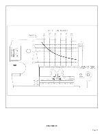
STAY WITHIN RATED PUNCHING CAPACITIES.
Your 6509-24M Ironworker is designed to operate in mild steel. Within conservative limits, it can also
operate in medium carbon annealed steel and some forms of abrasion resistant steels. Conditions of high
shock can be encountered when punching alloyed steels and, accordingly, the machine rating must be
reduced. THE MAXIMUM THICKNESS THAT CAN BE PUNCHED IS 3/4 OF AN INCH (20MM)
MILD STEEL.
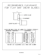
Punch to die clearance depends on material thickness.
Summary of Contents for IRONWORKER 6509-24M
Page 1: ...Page 1 MODEL 6509 24M IRONWORKER PRINTED MARCH 2005...
Page 9: ...Page 9 FIGURE 1...
Page 17: ...Page 17 FIGURE 5...
Page 19: ...Page 19 FIGURE 6...
Page 21: ...Page 21 FIGURE 7...
Page 31: ...Page 31 FIGURE 11...
Page 33: ...Page 33 FIGURE 12...
Page 35: ...Page 35 FIGURE 13...
Page 39: ...Page 39 FIGURE 15...
Page 41: ...Page 41 FIGURE 16...
Page 47: ...Page 47 FIGURE 20...
Page 51: ...Page 51 FIGURE 22...
Page 55: ...Page 55 FIGURE 25...
Page 59: ...Page 59 FIGURE 27...
Page 69: ...Page 69 FIGURE 30...
Page 71: ...Page 71 FIGURE 31...
Page 75: ...Page 75 FIGURE 34...
Page 79: ...Page 79 FIGURE 37...
Page 81: ...Page 81 FIGURE 38...
Page 85: ...Page 85 FIGURE 40 Serial s 5035FF1094 to 7124FF103...


