Page 27
6.1B STRIPPER ADJUSTMENT
CAUTION: TO PREVENT PUNCH BREAKAGE ON THE RETURN STROKE, THE STRIPPER
MUST BE ADJUSTED SO THAT THE BOTTOM OF THE STRIPPER IS PARALLEL WITH
THE MATERIAL BEING PUNCHED.
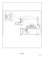
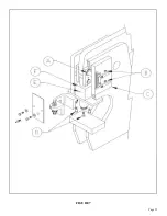
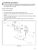
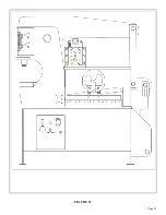
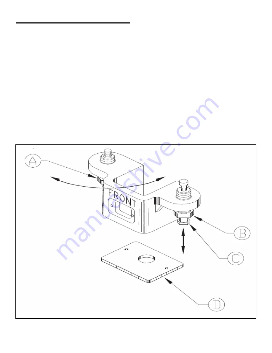
REFER TO FIGURE 10 BELOW.
TO ADJUST THE STRIPPER:
1.
The height of the stripper is adjusted using the adjustment bolts (A & B).
2.
The stripper is opened by pushing up on item (C) and swinging it out toward the front of the
machine.
3.
If you are punching light material or pieces too small to contact both sides of the stripper, install the
plate (D) on the bottom of the stripper.
4.
For maximum visibility and safety, always adjust the stripper down as close to the material as
possible.
FIGURE 10
Summary of Contents for IRONWORKER 6509-24M
Page 1: ...Page 1 MODEL 6509 24M IRONWORKER PRINTED MARCH 2005...
Page 9: ...Page 9 FIGURE 1...
Page 17: ...Page 17 FIGURE 5...
Page 19: ...Page 19 FIGURE 6...
Page 21: ...Page 21 FIGURE 7...
Page 31: ...Page 31 FIGURE 11...
Page 33: ...Page 33 FIGURE 12...
Page 35: ...Page 35 FIGURE 13...
Page 39: ...Page 39 FIGURE 15...
Page 41: ...Page 41 FIGURE 16...
Page 47: ...Page 47 FIGURE 20...
Page 51: ...Page 51 FIGURE 22...
Page 55: ...Page 55 FIGURE 25...
Page 59: ...Page 59 FIGURE 27...
Page 69: ...Page 69 FIGURE 30...
Page 71: ...Page 71 FIGURE 31...
Page 75: ...Page 75 FIGURE 34...
Page 79: ...Page 79 FIGURE 37...
Page 81: ...Page 81 FIGURE 38...
Page 85: ...Page 85 FIGURE 40 Serial s 5035FF1094 to 7124FF103...


