Page 42
7.3C BLADE REPLACEMENT
The lower blades are symmetrical and can be rotated to expose four cutting edges.
The upper blades have two cutting edges.
TO ROTATE OR REPLACE THE BLADES, USE THE FOLLOWING STEPS:
CAUTION: THE UPPER CASTING OF THE NOTCHER IS HEAVY ENOUGH TO CAUSE
INJURY IF DROPPED. USE CARE WHEN HANDLING THIS TOOL.
1.
Remove the return springs from the unit.
2.
Rotate or replace the upper blade and snug bolts only, to allow further adjustments.
3.
Rotate or replace the lower blades.
4.
Lower the upper blade down until it just passes the lower blade, approximately 1/16 of an inch
(1.5mm).
5.
Adjust the upper blade until the point almost touches the lower blades.
6.
Center the rear of the upper blade with the rear of the lower blades. There should be a clearance of
approximately .005 of an inch (.12mm) on each side.
7.
Tighten the upper blade bolts. To check blade alignment, raise and lower the upper casting several
times, by hand. After alignment, tighten the back up set screws, making sure that the upper blade
does not move.
7.4 RECTANGLE NOTCHER
The Rectangle Notcher is a component tool designed to make a 2 inch (50mm) wide notch in angle iron or
flat stock.
7.4A RECTANGLE NOTCHER INSTALLATION
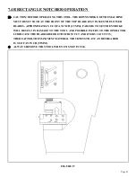
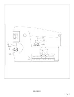
SEE FIGURE 17 ON THE FOLLOWING PAGE.
The Rectangle Notcher mounts only in the punch station on this model. The selector switch must be in the
PUNCH position to operate this tool.
TO MOUNT THE NOTCHER, remove the die holder and stripper. Mount the notcher so that the punch
ram lines up over the pressure block on the tool. With the bolts provided, anchor the tool to the punch
bolster.
Summary of Contents for IRONWORKER 6509-24M
Page 1: ...Page 1 MODEL 6509 24M IRONWORKER PRINTED MARCH 2005...
Page 9: ...Page 9 FIGURE 1...
Page 17: ...Page 17 FIGURE 5...
Page 19: ...Page 19 FIGURE 6...
Page 21: ...Page 21 FIGURE 7...
Page 31: ...Page 31 FIGURE 11...
Page 33: ...Page 33 FIGURE 12...
Page 35: ...Page 35 FIGURE 13...
Page 39: ...Page 39 FIGURE 15...
Page 41: ...Page 41 FIGURE 16...
Page 47: ...Page 47 FIGURE 20...
Page 51: ...Page 51 FIGURE 22...
Page 55: ...Page 55 FIGURE 25...
Page 59: ...Page 59 FIGURE 27...
Page 69: ...Page 69 FIGURE 30...
Page 71: ...Page 71 FIGURE 31...
Page 75: ...Page 75 FIGURE 34...
Page 79: ...Page 79 FIGURE 37...
Page 81: ...Page 81 FIGURE 38...
Page 85: ...Page 85 FIGURE 40 Serial s 5035FF1094 to 7124FF103...

