Page 46
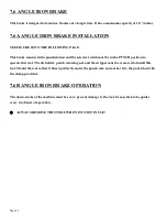
7.6 ANGLE IRON BRAKE
This brake is designed to form box frames out of angle iron. It has a maximum capacity of 1/4" (6mm).
7.6A ANGLE IRON BRAKE INSTALLATION
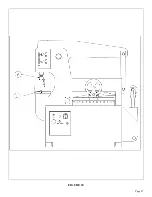
SEE FIGURE 20 ON THE FOLLOWING PAGE.
This brake mounts in the punch station and the selector switch must be in the PUNCH position to
operate this tool. The die holder, punch retaining nut and the stripper must be removed to install this
tool. Mount the tool so that it lines up directly under the punch ram and anchor it to the punch bed with
the clamp provided.
7.6B ANGLE IRON BRAKE OPERATION
The down-stroke of the machine must be set, to prevent damage to the tool. Grease the brake guides
every two hours of operation.
ALWAYS REMOVE THIS TOOL WHEN IT IS NOT IN USE!
Summary of Contents for IRONWORKER 6509-24M
Page 1: ...Page 1 MODEL 6509 24M IRONWORKER PRINTED MARCH 2005...
Page 9: ...Page 9 FIGURE 1...
Page 17: ...Page 17 FIGURE 5...
Page 19: ...Page 19 FIGURE 6...
Page 21: ...Page 21 FIGURE 7...
Page 31: ...Page 31 FIGURE 11...
Page 33: ...Page 33 FIGURE 12...
Page 35: ...Page 35 FIGURE 13...
Page 39: ...Page 39 FIGURE 15...
Page 41: ...Page 41 FIGURE 16...
Page 47: ...Page 47 FIGURE 20...
Page 51: ...Page 51 FIGURE 22...
Page 55: ...Page 55 FIGURE 25...
Page 59: ...Page 59 FIGURE 27...
Page 69: ...Page 69 FIGURE 30...
Page 71: ...Page 71 FIGURE 31...
Page 75: ...Page 75 FIGURE 34...
Page 79: ...Page 79 FIGURE 37...
Page 81: ...Page 81 FIGURE 38...
Page 85: ...Page 85 FIGURE 40 Serial s 5035FF1094 to 7124FF103...

