Page 50
7.8 PIPE NOTCHER
The Pipe Notcher is a component tool designed to saddle cut pipe or tubing for applications such as
railings. There are notchers available to notch angles in pipe and tubing, also. For prices and
availability, contact your local dealer or the factory.
7.8A PIPE NOTCHER INSTALLATION
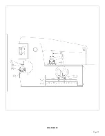
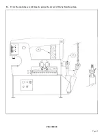
SEE FIGURE 22 ON THE FOLLOWING PAGE.
The pipe notcher can be installed in either the punch station or under the upper arm.
When installed on the tool table, the selector switch must be in the SHEAR position.
When installed in the punch station, the selector switch must be in the PUNCH position.
When installing the notcher in the punch station, remove the die holder and the stripper.
Install the pusher (F) on the punch ram, using the #45 punch retaining nut (C).
Set the notcher on the bolster with the cutting die facing either left or right and align the slug hole in the
notcher with the hole in the bolster. Anchor the tool with the finger clamps provided (D).
NOTE: ONE FINGER CLAMP WILL CLAMP THE NOTCHER BASE ON THE FRONT; THE
OTHER CLAMP BACKS UP THE TOOL.
To mount the notcher on the tool table, attach the riser (B) and the pusher (E) to the tool and align the
slug hole in the tool with the slug hole in the tool table. Anchor the tool to the tool table with the finger
clamps provided (D).
CAUTION: WITH THE TOOL MOUNTED IN EITHER STATION, IT IS NECESSARY TO SET
THE DOWNSTROKE OF THE MACHINE TO PREVENT DAMAGE TO THE TOOL. THE
UPPER DIE SHOULD NOT PASS THE LOWER DIE BY MORE THAN 1/32 OF AN INCH
(.7MM).
Summary of Contents for IRONWORKER 6509-24M
Page 1: ...Page 1 MODEL 6509 24M IRONWORKER PRINTED MARCH 2005...
Page 9: ...Page 9 FIGURE 1...
Page 17: ...Page 17 FIGURE 5...
Page 19: ...Page 19 FIGURE 6...
Page 21: ...Page 21 FIGURE 7...
Page 31: ...Page 31 FIGURE 11...
Page 33: ...Page 33 FIGURE 12...
Page 35: ...Page 35 FIGURE 13...
Page 39: ...Page 39 FIGURE 15...
Page 41: ...Page 41 FIGURE 16...
Page 47: ...Page 47 FIGURE 20...
Page 51: ...Page 51 FIGURE 22...
Page 55: ...Page 55 FIGURE 25...
Page 59: ...Page 59 FIGURE 27...
Page 69: ...Page 69 FIGURE 30...
Page 71: ...Page 71 FIGURE 31...
Page 75: ...Page 75 FIGURE 34...
Page 79: ...Page 79 FIGURE 37...
Page 81: ...Page 81 FIGURE 38...
Page 85: ...Page 85 FIGURE 40 Serial s 5035FF1094 to 7124FF103...

