Page 58
7.12 OPTIONAL GAUGING EQUIPMENT
7.12A 54 INCH (137 CM) DELUXE BACK GAUGE
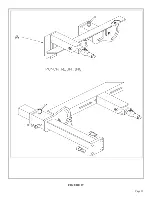
The 54 inch (138cm) back gauge mounts on the drop-off side of the machine and will reach all three
stations from one point. It is designed to be used as a length stop in the shear, punch and tooling stations.
For the proper configuration for each station, SEE FIGURE 27 ON THE FOLLOWING PAGE.
7.12B MITER TABLE (BAR SHEAR)
The optional miter table is designed for use in the bar shear. It mounts in place of the standard shear
table. It has a guide built in to allow easy positioning of material to be cut at various angles, as well as
straight cutting. For parts identification, see the Tooling Parts Manual.
7.12C PUNCH TABLE
The optional punch gauging table is designed to replace the standard table. It is equipped with quick
set-up guides for a wide variety of punching applications. For parts identification, see the Tooling Parts
Manual.
7.12D JOG CONTROL
The jog control is an optional electrical hand control that allows jogging of the machine in either the
punch or the shear position. It can be used in a variety of functions, such as setting up various bends on
brake tools. When the machine is in the JOG position, the foot switch is inoperative.
Summary of Contents for IRONWORKER 6509-24M
Page 1: ...Page 1 MODEL 6509 24M IRONWORKER PRINTED MARCH 2005...
Page 9: ...Page 9 FIGURE 1...
Page 17: ...Page 17 FIGURE 5...
Page 19: ...Page 19 FIGURE 6...
Page 21: ...Page 21 FIGURE 7...
Page 31: ...Page 31 FIGURE 11...
Page 33: ...Page 33 FIGURE 12...
Page 35: ...Page 35 FIGURE 13...
Page 39: ...Page 39 FIGURE 15...
Page 41: ...Page 41 FIGURE 16...
Page 47: ...Page 47 FIGURE 20...
Page 51: ...Page 51 FIGURE 22...
Page 55: ...Page 55 FIGURE 25...
Page 59: ...Page 59 FIGURE 27...
Page 69: ...Page 69 FIGURE 30...
Page 71: ...Page 71 FIGURE 31...
Page 75: ...Page 75 FIGURE 34...
Page 79: ...Page 79 FIGURE 37...
Page 81: ...Page 81 FIGURE 38...
Page 85: ...Page 85 FIGURE 40 Serial s 5035FF1094 to 7124FF103...

