Page 64
8.5 CYLINDER SEAL REPLACEMENT
Use the following steps to replace the seals in the hydraulic cylinder:
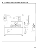
SEE FIGURE 28 ON THE FOLLOWING PAGE. IF YOUR MACHINE HAS A DIFFERENT STYLE
OF CYLINDER, REFER TO SECTION 10.0.
1.
With the selector switch in the SHEAR position and the arms up, turn the machine’s power off at
the disconnect switch and lock it.
2.
Block the arms up, either on the tool table or under the shear arm. SEE ITEM A.
3.
Remove the hydraulic hoses from the cylinder and allow the oil to drain from the cylinder.
4.
Remove the cylinder clevis pin (D) and swing the cylinder out away from the arm.
5.
The cylinder head (B) is threaded into the cylinder.
6.
Use a pin wrench to unscrew the cylinder head from the cylinder tube.
7.
Place a rod through the cylinder clevis and pull the cylinder apart, using a come-a-long or similar
device.
8.
Remove the locking nut from the end of the cylinder shaft and slide the piston and the head off of
the shaft.
9.
Replace all of the seals. There will be extra seals in the kit. Match up the replacement seals with the
old ones and discard the rest.
10. Clean all of the parts, including the inside of the cylinder tube, and check all parts for nicks and
scratches.
11. Oil all of the seals before reassembling the cylinder.
12. After the piston and head are assembled on the shaft, they can be tapped back into the tube with a
brass or plastic hammer.
13. Re-thread the cylinder head into the tube.
14. Reconnect the hoses to the cylinder.
15. Use care removing the blocking device (A) from under the arms. Since the cylinder does not contain
oil, it may drop some when the blocks are removed.
Summary of Contents for IRONWORKER 6509-24M
Page 1: ...Page 1 MODEL 6509 24M IRONWORKER PRINTED MARCH 2005...
Page 9: ...Page 9 FIGURE 1...
Page 17: ...Page 17 FIGURE 5...
Page 19: ...Page 19 FIGURE 6...
Page 21: ...Page 21 FIGURE 7...
Page 31: ...Page 31 FIGURE 11...
Page 33: ...Page 33 FIGURE 12...
Page 35: ...Page 35 FIGURE 13...
Page 39: ...Page 39 FIGURE 15...
Page 41: ...Page 41 FIGURE 16...
Page 47: ...Page 47 FIGURE 20...
Page 51: ...Page 51 FIGURE 22...
Page 55: ...Page 55 FIGURE 25...
Page 59: ...Page 59 FIGURE 27...
Page 69: ...Page 69 FIGURE 30...
Page 71: ...Page 71 FIGURE 31...
Page 75: ...Page 75 FIGURE 34...
Page 79: ...Page 79 FIGURE 37...
Page 81: ...Page 81 FIGURE 38...
Page 85: ...Page 85 FIGURE 40 Serial s 5035FF1094 to 7124FF103...

