background image

Page 82

10.0 SUPPLEMENT FOR OLDER MODELS

10.1 CYLINDER SEAL REPLACEMENT

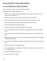
Use the following steps to replace the seals in the hydraulic cylinder: 

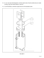
SEE FIGURE 39 ON THE FOLLOWING PAGE. 

1.

With the selector switch in the SHEAR position and the arms up, turn the machine’s power off at 

the disconnect switch and lock it. 

2.

Block the arms up, either on the tool table or under the shear arm. SEE ITEM (A). 

3.

Remove the hydraulic hoses from the cylinder and allow the oil to drain from the cylinder. 

4.

Remove the cylinder clevis pin (D) and swing the cylinder out away from the arm. 

5.

The cylinder head (B) is threaded into the cylinder. 

6.

Use a pin wrench to unscrew the cylinder head from the cylinder tube. 

7.

Place a rod through the cylinder clevis and pull the cylinder apart, using a come-along or similar

device. 

8.

Remove the locking nut from the end of the cylinder shaft and slide the piston and head off of the

shaft.

9.

Replace all of the seals. There will be extra seals in the kit. Match up the replacement seals with the

old ones and discard the rest. 

10. Clean all of the parts, including the inside of the cylinder tube, and check all parts for scratches and

nicks.

11. Oil all of the seals before reassembling the cylinder.

12. After the piston and head are assembled on the shaft, they can be tapped back into the tube with a

brass or plastic hammer.

13. Re-thread the cylinder head into the tube.

14. Reconnect the hoses to the cylinder.

Summary of Contents for IRONWORKER 6509-24M

Page 1: ...Page 1 MODEL 6509 24M IRONWORKER PRINTED MARCH 2005...

Page 2: ...NTENANCE 18 21 5 1 Lubrication 18 5 2 Routine Lubrication 18 19 5 3 Scheduled Maintenance 20 21 6 0 MACHINE OPERATION 22 33 6 1 Punch Operation 22 26 6 1B Stripper Adjustment 27 6 2 Bar Shear Operatio...

Page 3: ...ROUBLE SHOOTING GUIDE 60 65 8 1 Electrical Trouble Shooting Motor 60 61 8 2 Limit Switch Inspection 62 8 3 Control Valve Inspection 62 63 8 4 Hydraulics 63 8 5 Cylinder Seal Replacement 64 65 9 0 IRON...

Page 4: ...at any point in the stroke stop jog or reverse gives the Scotchman 6509 24M Ironworker a tremendous advantage over mechanical ironworkers There is no chance of the Scotchman being accidentally trippe...

Page 5: ...hould also wear steel toed shoes and tight fitting leather gloves 5 Strictly comply with all warning labels and decals on the machine Never remove any of the labels Replace worn or damaged labels prom...

Page 6: ...ordance with the manufacturer s instructions 13 A safety VHS tape was mailed to you or shipped with the machine If you did not receive it please contact the factory or your local dealer immediately an...

Page 7: ...odified in any way or subjected to abusive and abnormal use inadequate maintenance and lubrication or subjected to use beyond the seller s recommended capacities and specifications In no event shall s...

Page 8: ...003145 REMOVE TOOL L 003110 PUNCH DIE WARNING M 003115 DO NOT REMOVE N 003125 KEEP HANDS CLEAR O 003130 30 TON OFFSET P 019101 HEAVY END DECAL Q 003100 WARNING LABEL R 003120 DANGER VOLTAGE LABEL S 00...

Page 9: ...Page 9 FIGURE 1...

Page 10: ...Page 10 4 0 INSTALLATION SET UP CAUTION THIS SECTION DISCUSSES INSTALLATION AND SET UP PROCEDURES PLEASE READ THOROUGHLY BEFORE OPERATING THIS MACHINE FIGURE 2...

Page 11: ...Floor to top of die holder 40 7 8 103 8 C Floor to punch bolster 36 91 4 D Floor to bottom rail 3 3 4 9 5 E Floor to Bar Shear 28 1 2 72 4 F Floor to tool table 42 1 2 107 9 G Height 66 167 6 H Lengt...

Page 12: ...1 250 Kg Check the capacity of the lifting equipment before attempting to move the machine THIS MACHINE IS TOP HEAVY AND SHOULD BE MOVED WITH CARE AND ON FLAT SURFACES ONLY This is the quickest and sa...

Page 13: ...rol handles and limit switches B Pump and motor assembly C Hydraulic hoses and fittings D Starter box and control box E Electrical connections F Control valve The reservoir is full of oil The recommen...

Page 14: ...performance the supply voltage should be or 10 of the motor voltage rating Check the motor data tag for full load current requirements The electrical diagram for the machine is inside the cover of th...

Page 15: ...ions are clear TO POWER THE MACHINE place the disconnect switch in the ON position and the selector switch in the START position Momentarily power the machine by pushing the green START button and hav...

Page 16: ...T position and power the machine Place the selector switch in the PUNCH position Measure the distance from the punch ram to the top of the bolster The distance should be 8 13 16 inches 224mm Switch th...

Page 17: ...Page 17 FIGURE 5...

Page 18: ...irt can or a spray applicator 5 2 ROUTINE LUBRICATION Grease the main pins A B and the punch ram D daily SEE FIGURE 6 ON THE FOLLOWING PAGE Grease all other fittings twice per week Mobil grease XHP222...

Page 19: ...Page 19 FIGURE 6...

Page 20: ...ve the punch ram and the bushing Care should be taken when removing these parts THEY ARE HEAVY 6 Clean all grease and dirt off both parts and check the clearance between the outside diameter of the pu...

Page 21: ...Page 21 FIGURE 7...

Page 22: ...Page 22 6 0 MACHINE OPERATION 6 1 PUNCH OPERATION ALWAYS WEAR SAFETY GLASSES THE FIRST AND MOST IMPORTANT PROCEDURE IS THE PROPER METHOD OF CHANGING AND ALIGNING PUNCHES AND DIES FIGURE 8...

Page 23: ...etaining nut and punch aside 5 Loosen the two set screws D holding the die insert C Remove the die insert and loosen the set screw holding the die on remove it and set it aside CAUTION IF YOU ARE USIN...

Page 24: ...itch in the START position and power the machine 23 Place the selector switch in the SHEAR position To be sure that the clearance is correct jog the machine several times with the foot switch without...

Page 25: ...10 holes E PUNCH FULL AND COMPLETE HOLES DO NOT PUNCH PARTIAL HOLES The side thrust encountered in punching a partial hole can force the punch over against the die and result in punch or die breakage...

Page 26: ...steel should have a minimum of 1 16 inch clearance Punch diameter 1 16 Die diameter In thin materials the recommended punch to die clearance is 1 10 of the material thickness We do not recommend less...

Page 27: ...IPPER 1 The height of the stripper is adjusted using the adjustment bolts A B 2 The stripper is opened by pushing up on item C and swinging it out toward the front of the machine 3 If you are punching...

Page 28: ...int For applications that do not require the maximum tonnage move the material to the right for minimal distortion on the drop piece Do not attempt to shear pieces that are too short for the hold down...

Page 29: ...symmetrical and can be rotated to expose four 4 cutting edges For recommended clearances SEE FIGURE 12 ON PAGE 33 B ALL CUTS SHOULD BE MADE AS FAR FROM THE ARM PIVOT AS POWER WILL PERMIT The Shear Bl...

Page 30: ...essure plate adjustment before resetting the rub blocks 3 For the pressure plate adjustment loosen the lock nuts B on the four adjusting screws that engage the pressure plate A 4 Tighten all four adju...

Page 31: ...Page 31 FIGURE 11...

Page 32: ...support C Do not tighten so as to compress paper shims between the blades Tighten the 4 socket head retaining screws D to approximately 100 ft lbs torque and lock the back up screws E with the lock n...

Page 33: ...Page 33 FIGURE 12...

Page 34: ...this machine SAFETY GLASSES ARE REQUIRED when using optional tools of any type Each self contained tool has its own stroke and tonnage requirements This section will cover the operation and location o...

Page 35: ...Page 35 FIGURE 13...

Page 36: ...slide the workpiece freely through the unit The lower stroke should be set so that the upper blade point enters the lower blades approximately 1 8 inch 3mm 7 1B 6 X 6 ANGLE SHEAR OPERATION Oil must b...

Page 37: ...ANGLE SHEAR SHOULD JAM FOR ANY REASON DO NOT ATTEMPT TO FREE IT BY HAND USE A PRY BAR OR SIMILAR DEVICE REPLACE THE BLADES OR INSTALL SHIMS DEPENDING ON WHAT CAUSED THE JAM REMOVE THE TOOL WHEN IT IS...

Page 38: ...e set when using the rod shear Set the upstroke of the machine so that the workpiece easily slides through the tool Set the down stroke so that the cut can be made with a minimum amount of stroke 7 2B...

Page 39: ...Page 39 FIGURE 15...

Page 40: ...tension of the tool The lower stroke must be set so that the upper blade just passes the lower blades at the point of the vee by no more than 1 16 of an inch 1 5mm To install the notcher under the upp...

Page 41: ...Page 41 FIGURE 16...

Page 42: ...the upper blade with the rear of the lower blades There should be a clearance of approximately 005 of an inch 12mm on each side 7 Tighten the upper blade bolts To check blade alignment raise and lowe...

Page 43: ...ASSES THE LOWER BLADES APPROXIMATELY 1 8 OF AN INCH 1 5MM FAILURE TO SET THE STROKE WILL RESULT IN DAMAGE TO THE TOOL AND POSSIBLE INJURY TO THE OPERATOR LUBRICATE THE BLADES BEFORE THE FIRST CUT AND...

Page 44: ...three lengths of brakes available for this model 12 18 and 24 inch The brakes mount under the upper arm in the tool station and are held down with the finger clamps provided Mount the 12 and 18 inch b...

Page 45: ...not return usually a slight tap on the upper die is sufficient to free the guides DO NOT ATTEMPT TO FREE THE BRAKE BY HAND Sticking can be caused by lack of lubrication complexity of the part being be...

Page 46: ...ust be in the PUNCH position to operate this tool The die holder punch retaining nut and the stripper must be removed to install this tool Mount the tool so that it lines up directly under the punch r...

Page 47: ...Page 47 FIGURE 20...

Page 48: ...tool Before installing the tool remove the upper blade Install the spring guide pins with the head down in the side plate of the shear REFER TO THE INSERT IN FIGURE 21 BELOW Slide the return springs o...

Page 49: ...nst the fixed vertical blades Now check to see that the blades have good alignment front and back and have maintained their perpendicularity to the lower blades POSITION THE ADJUSTING HANDLE The adjus...

Page 50: ...remove the die holder and the stripper Install the pusher F on the punch ram using the 45 punch retaining nut C Set the notcher on the bolster with the cutting die facing either left or right and alig...

Page 51: ...Page 51 FIGURE 22...

Page 52: ...rings into the housing and check the gap SEE FIGURE 23 BELOW If proven correct tighten the two M 10 socket head screws holding the die section in place Apply some high pressure lube all around the ins...

Page 53: ...THE DOWNSTROKE OF THE MACHINE WILL RESULT IN DAMAGE TO THE TOOL 1 Set the down stroke of the machine so that the upper die clears the lower die by twice the wall thickness of the tube plus 1 32 of an...

Page 54: ...the finger clamps B provided 4 Set the upstroke of the machine so that the size of tube you want to shear will feed through the tool Make sure that the upstroke is set so that there is spring tension...

Page 55: ...Page 55 FIGURE 25...

Page 56: ...TION Failure to set the stroke will allow the punch retaining nut to strike the die holder causing damage to the machine and possible injury to the operator Because of its design the offset die holder...

Page 57: ...leted by following instructions in SECTION 6 1 tighten the brass billet against the ram threads Remember to loosen the brass billet before removing the retaining nut This retaining nut requires a pin...

Page 58: ...s a guide built in to allow easy positioning of material to be cut at various angles as well as straight cutting For parts identification see the Tooling Parts Manual 7 12C PUNCH TABLE The optional pu...

Page 59: ...Page 59 FIGURE 27...

Page 60: ...Check the motor rotation It should be counterclockwise when facing the shaft end of the motor 2 Check the selector switch It must be in either the PUNCH or the SHEAR position or the machine will not...

Page 61: ...adings are not correct continue on with the following steps A Turn the machine s power off at the disconnect switch Remove the cover on the foot switch and check for any loose connections B Make sure...

Page 62: ...is a pin in the center of the knurled nut that holds the coil on To shift the spool manually use a small punch or similar device to push these pins in by hand first one and then the other Turn the mac...

Page 63: ...cylinder or pump There is a pressure port for a pressure gauge provided on all machines The port will be on the valve manifold or the pressure line between the pump and the valve A gauge with a minimu...

Page 64: ...rom the cylinder tube 7 Place a rod through the cylinder clevis and pull the cylinder apart using a come a long or similar device 8 Remove the locking nut from the end of the cylinder shaft and slide...

Page 65: ...Page 65 16 Cycle the machine several times to purge the air out of the hydraulic system FIGURE 28...

Page 66: ...6250 Lower Blade Holder F 007100 Shear Table G 007249 Main Pin Bushing H 006129 Shear Arm Pin I 080174 Grease Bolt J 010177 Pressure Plate K 007273 Brass Plate 2 Required L 218120 M 12 Set Screw M 210...

Page 67: ...Page 67 BB 214012 M 10 Washer CC 212014 M 12 Lock Washer DD 214014 M 12 Washer EE 214017 M 16 Washer FF 212012 M 10 Lock Washer FIGURE 29...

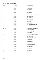
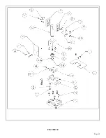
Page 68: ...34402 Punch Plate J 230107 M 8 FSHCS K 016095 40 Punch Retaining Nut L 221312 M 12 SHCS M W 010220 Punch Ram Bushing Set N 007232 Lower Punch Pin O 016063 1 1 2 Snap Ring P 016620 2 Snap Ring Q 006174...

Page 69: ...Page 69 FIGURE 30...

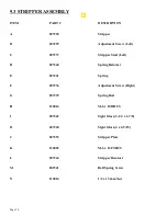
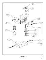
Page 70: ...tud Left D 007240 Spring Retainer E 007241 Spring F 007236 Adjustment Screw Right G 007239 Spring Rod H 220014 M 6 x 10 BHCS I 007242 Sight Glass 3 1 4 x 1 7 8 I1 007248 Sight Glass 4 x 2 5 15 J 00725...

Page 71: ...Page 71 FIGURE 31...

Page 72: ...9 4 UPPER ARM ASSEMBLY ITEM PART DESCRIPTION A 007220 Upper Arm Includes A B D F B 010176 Bushing C 080174 Grease Bolt D 007226 Upper Arm Bushing E 006130 Upper Arm Pin F 006174 Punch Pin Bushing FIG...

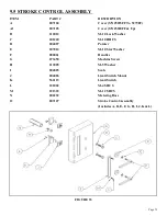
Page 73: ...10 Lock Washer C 201220 M 10 HHCS D 004087 Pointer E 207012 M 10 Star Washer F 080061 Handles G 073450 Machine Screw H 213005 M 5 Washer I 004085 Scale J 004086 Limit Switch Mount K 562113 Limit Swit...

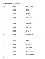
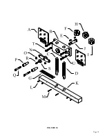
Page 74: ...5 Label Hands Clear H 080348 Gear Center I 080349 Gear Right J 080338 Wheel Shaft K 080344 Base L 220026 M 6 BHCS M 141415 1 4 x 1 3 4 Roll Pin N 017346 Hold Down Crank Inc O P Q O 210014 M 12 Jam Nut...

Page 75: ...Page 75 FIGURE 34...

Page 76: ...006230 Clevis Pin B 007403 Cylinder Clevis C 007404 Cylinder D 007426 Cylinder Anchor Pin E 016063 1 1 2 Snap Ring F 006235 Cylinder Shroud G 224205 M 10 WLCS H 007162 Rear Shroud I 007152 Front Shro...

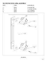
Page 77: ...Page 77 9 8 CONNECTING LINK ASSEMBLY ITEM PART DESCRIPTION A 007263 Connecting Link B 006160 Connecting Link Pins C 016063 1 1 2 Snap Ring D 243101 M 6 Grease Zerk FIGURE 36...

Page 78: ...6560 Complete Power Unit Less Motor I 007400 Cylinder J 003880 O Ring Adaptor K 003915 Return Hose L 003920 Hose M 003830 90 Degree SAE Adaptor N 201210 M 10 HHCS O 212012 M 10 Lock Washer P 003925 Su...

Page 79: ...Page 79 FIGURE 37...

Page 80: ...Punch Shear 011844 Selector Switch Knob G 011846 Coil H 011948 Start Switch Lamp I 562453 Foot Switch 011753 Cord Foot Switch 562452 Micro Switch Foot Switch J 562023 Run Jog Switch Optional K 004524...

Page 81: ...Page 81 FIGURE 38...

Page 82: ...ylinder 6 Use a pin wrench to unscrew the cylinder head from the cylinder tube 7 Place a rod through the cylinder clevis and pull the cylinder apart using a come along or similar device 8 Remove the l...

Page 83: ...oving the blocking device A from under the arms Since the cylinder does not contain oil it may drop some when the blocks are removed 16 Cycle the machine several times to purge the air out of the hydr...

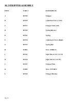
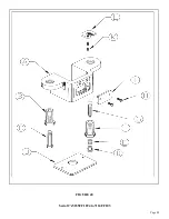
Page 84: ...ew Left C 007237 Stripper Stud Left D 007240 Spring Retainer E 007241 Spring F 007236 Adjustment Screw Right G 007239 Spring Rod H 220014 M 6 x 10 BHCS I 007242 Sight Glass 3 1 4 x 1 7 8 I1 007248 Sig...

Page 85: ...Page 85 FIGURE 40 Serial s 5035FF1094 to 7124FF103...

Reviews: