Page 16
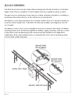
10.1 MATERIAL SUPPLY TRACKS
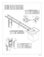
A 10’ and 20’ roller supply track is an available option for this saw. They can be bolted to the input side
of the saw (either the left or right hand side) to support longer pieces of material. If a longer supply track
is needed, these can be bolted together, end to end. The ten foot supply track shown here bolts to the left
side of the machine, to the base casting.
SEE THE DRAWING ON THE FOLLOWING PAGE.
1.
Attach the Conveyor Connector to the left side of the base casting of the saw, as shown on the next
page. The Right-Side version has a different Support Bracket, but everything else is the same.
2.
Bolt the Upper Leg to the Conveyor. The easiest way is to lay the Conveyor on the floor, top-side
down, and bolt the Upper Leg on. See the Upper parts group. The Upper Leg can be positioned
anywhere along the Conveyor, but further from the saw is better.
3.
Measure from the floor up to the Top of the Conveyor Connector.
4.
Bolt the Lower Leg to the Upper Leg, using this measurement. With the Conveyor still top-side
down, measure up from the floor to the bottom of the Lower Leg - where it will contact the floor -
and bolt the Lower Leg on. Final adjustment is done when it is attached to the saw.
5.
With the Conveyor/Leg Assembly right-side up, bolt it to the saw via the Conveyor Connector, as
shown on the next page. End Brackets may have to be mounted on the Conveyor as shown, first.
6.
Adjust the Leg so that the Conveyor is Level and Square to the saw. Make sure that the rollers on
the Conveyor are the same height as the Saw Bed. Adjust where needed.
7.
The Legs may be anchored to the floor, using the mounting bolts provided.
Summary of Contents for SU-280-G
Page 1: ...Page 1 MODEL SU 280 G BAND SAW...
Page 5: ...3 2 SELECTION OF THE BAND SAW Page 5...
Page 17: ...Page 17...
Page 19: ...Page 19...
Page 20: ...Page 20 11 0 DRAWINGS SCHEMATICS 11 1 ELECTRICAL SCHEMATIC...
Page 21: ...Page 21...
Page 22: ...Page 22 11 2 MACHINE EXPLODED VIEW...
Page 23: ...Page 23...


