Page 18
10.2 DISCHARGE TRACKS WITH SCALES
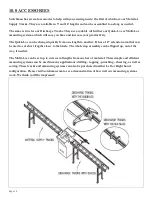
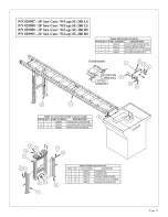
Roller discharge tracks, equipped with either a Right or Left-Hand Quick-Loc, are available in 5’ and
10’ lengths. If the Left-Hand Quick-Loc is used, we have 10’ and 20’ Right Hand Conveyors available.
The discharge track shown mounts to the machine in place of the 30" stop that comes with the machine.
The discharge tracks allow fast set-up and accuracy for various lengths of cuts.
SEE THE DRAWING ON THE FOLLOWING PAGE.
1.
Bolt the Support Bracket to the right side of the base casting, with one of the (3) M-10 bolts, washers and nuts. The other
two are used to attach the Conveyor to the Support Bracket. The above are contained in the P/N 028656 - REPAC BOX
SU-280 RS (Right-Side). P/N 028682 REPAC BOX SU-280 LS (Left side) has a different Support Bracket, but
everything else is the same.
2.
Bolt the Upper Legs to the Conveyor. The easiest way is to lay the Conveyor on the floor, top-side down, and bolt the
Upper Legs on. The Legs can be mounted anywhere along the Conveyor, but should be mounted towards the end of it.
3.
Use a straight edge and hold it flat down on the bed of the saw. Measure from the floor up to the bottom of the straight
edge. Use this measurement when bolting the Lower Legs to the Upper Legs. With the Conveyor still top-side down,
measure from the floor up to the bottom of the lower legs -where they will contact the floor - and bolt the Lower Legs on.
Final adjustment is made when the Conveyor is mounted to the Saw.
4.
With the Conveyor/Leg Assembly right-side up, bolt it to the Support Bracket, as shown on the next page. End Brackets
may have to be mounted on the Conveyor as shown, first. It is Very Important that the Conveyor is Square and Level to
the saw. Make adjustments where needed.
5.
Next, the (4) Aluminum Brackets should be bolted to the bottom of the Aluminum Rail. The Carriage Bolt goes in the
Center Slot of the Aluminum Bracket and is encapsulated when the Bracket is bolted to the bottom of the Rail - but still
moves, allowing adjustment. Two Brackets are located 10-1/2" in from the ends of the Aluminum Rail and two Brackets
are 10-1/2" out from the center of the Aluminum Rail. Make sure that the serrations (or teeth) on the Aluminum Rail
face towards the back and insert the Carriage Bolts in the holes in the Conveyor. Use the Flat Washers and loosely
thread the Nuts onto the Carriage Bolts. Make sure that the Aluminum Rail is Square to the Saw and the Conveyor;
then, tighten the nuts.
6.
Next, assemble the Quick-Loc Arm as shown in the drawing. The P/N 029114 - 10" Quick-Loc Arm is for cutting short
pieces and is not needed for now. Do not over-tighten Item 4 - Shoulder Bolt. Item 3 - 12 x 2 Extension - should flip up
with a little tension. When the Quick-Loc Arm Assembly is assembled, squeeze the handle and slide it onto the
Aluminum Rail. Make sure that Items 1 and 10 are adjusted correctly. 1 is to limit the movement of the Stop when the
material is pushed against it. 10 is to keep the Stop Level.
7.
Next, the Measuring Tape needs to be applied to the Aluminum Rail and should be done as follows: Securely set the
Quick-Loc Arm about 20" from the Saw Blade. Cut a piece of material at this length, making sure that there are no
burrs or metal chips on the material. This is a critical cut as it will be used to determine the position of the Measuring
Tape. Do NOT move the -L Stop Assembly after you have made the cut. Measure the length of the cut. Slide the
Measuring Tape under the Q-L Stop Assembly in the groove on the Aluminum Rail, with backer still attached to the
Measuring Tape. Remove 3 or 4 inches of the backer and align the Tape to the Pointer on the Q-L Stop Assembly to
the length of the cut material.,
8.
Set the rest of the Measuring Tape in the Groove (with backer still on) and remove the Quick-Loc Arm Assembly from
the Aluminum Rail. Remove the backer from the rest of the tape and, using only light tension, apply the remainder of
the Measuring Tape to the Groove. Trim unused Measuring Tape from the ends of the Aluminum Rail.
9.
Reinstall the Quick-Loc Arm Assembly and make a test cut to verify that the Measuring Tape is accurate. The Pointer
on the Q-L Stop Assembly is adjustable (about 3/4") if you’re off a little. Once you verify that the Measuring Tape is
correctly installed, you’re done. The Quick-Loc is ready for use.
Summary of Contents for SU-280-G
Page 1: ...Page 1 MODEL SU 280 G BAND SAW...
Page 5: ...3 2 SELECTION OF THE BAND SAW Page 5...
Page 17: ...Page 17...
Page 19: ...Page 19...
Page 20: ...Page 20 11 0 DRAWINGS SCHEMATICS 11 1 ELECTRICAL SCHEMATIC...
Page 21: ...Page 21...
Page 22: ...Page 22 11 2 MACHINE EXPLODED VIEW...
Page 23: ...Page 23...


