background image

Page 11

7.1 ADJUSTMENT OF CUTTING BLADE GUIDES

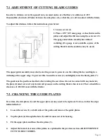
In order to obtain a correctly squared cut, you must make sure that there is a distance of .035 

thousandths of an inch (0.9 mm) between the side plates (3), so that they are all in contact with the blade.

To adjust this distance, follow the instructions given below:


1. Loosen screws (1)

2. Place a .035" (0.9 mm) gauge or sheet between the 

plates and adjust the distance using the set screw (2). 

The gauge must slide smoothly but without 

wobbling. (If a gauge is not available, a piece of the 

cutting blade from the machine may be used.)

The upper guide assembly may also be exerting excessive pressure on the cutting blade, resulting in a 

widening at the upper edge. To prevent this, loosen the screws (6) and slightly raise the blade guide (7). 

The guide must be positioned so that after rotating the saw when it is not in contact with any material, 

the plate (4) must not exert any downward pressure on the cutting blade when at rest. (There should be a 

clearance of .004 (0.1 mm) with the blade.)

7.2. CHANGING THE GUIDE PLATES

Over time, the side plates (3) and the upper plate (4) may need to be replaced. To do so, follow the steps 

indicated below:

1.

Loosen the screws (1) on both sides of the guide and remover the guide plates.

2.

Tap the plate (4) through the hole (5) until it comes out of its housing.

3.

Fit the upper plate and then the side plates (3).

4.

Adjust the lateral clearance of the plates, as explained in the previous section, ADJUSTMENT OF 

CUTTING BELT GUIDES.

Summary of Contents for SU-280

Page 1: ...Page 1 MODEL SU 280 BAND SAW PRINTED JULY 2013...

Page 2: ...Connection to the Electric System 7 5 3 Installing the Band Saw Blade 7 5 4 Cutting Coolant 8 6 INSTRUCTIONS FOR USE 8 6 1 Proper and Improper Use 8 6 2 Function of the Operating Mechanisms 8 6 3 Rai...

Page 3: ...vent contact with hazardous areas of the machine EN 60204 1 Electrical equipment of industrial machines EN 13850 Machine safety emergency stop equipment 2006 42 CEE on Machine Safety 93 68 CEE on the...

Page 4: ...well as the name of the part and the code that appear in the last chapter of exploded views 3 0 TECHNICAL DATA MAIN MOTOR POWER TRIF 2 VEL MONOF 1 5 HP MOTOR SPEED3000 1500 RPM 3 000 1 500 RPM 1 500 R...

Page 5: ...Page 5 3 2 SELECTION OF THE BAND SAW...

Page 6: ...ic CAUTION Do not improperly dispose of the packaging Send the materials to be recycled or eliminated in accordance with current legislation 5 0 INSTRUCTIONS FOR ANCHORING SERVICE START UP 5 1 ANCHORI...

Page 7: ...gain The pneumatic connection must be made to the supply system using a connector that is appropriate for the connector on the machine Adjust the pressure at the filtering group 5 3 INSTALLING THE BAN...

Page 8: ...fe of the saw 6 0 INSTRUCTIONS FOR USE 6 1 PROPER AND IMPROPER USE Band saw machine for cutting all kinds of ferrous and non ferrous materials Use of the machine for cutting other materials is prohibi...

Page 9: ...n the arc bolt to adjust the height WARNING When performing the cut it is important that the saw should be lowered at a constant rate with no sharp changes of speed If the saw becomes jammed in the ma...

Page 10: ...on of the blade guide plates Guide adjustment See Section 7 1 Excessive wear on blade Tension too low or too high See Section 5 3 Guide plates worn Excessive pressure from upper plate See Section 7 1...

Page 11: ...cutting blade resulting in a widening at the upper edge To prevent this loosen the screws 6 and slightly raise the blade guide 7 The guide must be positioned so that after rotating the saw when it is...

Page 12: ...e It is mandatory to use officially approved work clothing which must be fastened Before starting work the operator must be sure to remove all tools and wrenches that have been used for any maintenanc...

Page 13: ...e keys must be placed under the care of qualified personnel Before taking any repairs on electrical devices disconnect the plug from the power supply In the event that extension cords are used ensure...

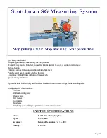
Page 14: ...hanged quickly from one length to another It has a 10 extension arm that can be used to cut short lengths closer to the blade The whole stop assembly can be flipped up out of the way if needed The Mul...

Page 15: ...ions or switchtometricmode Adjustablestop Flipstop canbeflippedup awayfromtabletobackfeed Portablepowerhead quicklydetachesfromrail List storage Holds10listswithupto10moveseach Quickandeasycalibration...

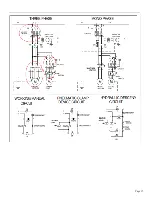
Page 16: ...Page 16 11 0 DRAWINGS SCHEMATICS 11 1 ELECTRICAL SCHEMATIC...

Page 17: ...Page 17...

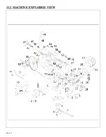
Page 18: ...Page 18 11 2 MACHINE EXPLODED VIEW...

Page 19: ...Page 19 11 3 HYDRAULIC DESCENT EXPLODED VIEW...

Page 20: ...Page 20...

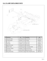
Page 21: ...Page 21 11 4 CLAMP EXPLODED VIEW...

Page 22: ...Page 22 11 5 GUIDES EXPLODED VIEW...

Reviews: