4. INSTRUCTIONS FOR ANCHORING / SERVICE START-UP
4.1 Anchoring Instructions
Ensure that the machine has not suffered any damage during transport by making an initial visual
inspection. If damage is observed, advise the carrier immediately.
The machine must be installed on a firm surface that is as level as possible, in order to reduce vibrations
during operation and so that it operates within the parameters established by the manufacturer.
4.2 Power Supply Connection
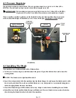
ATTENTION: The pneumatic working pressure must be between 6.5 to 7.2 Bar (95 to 105 PSI ).
Page 9
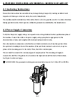
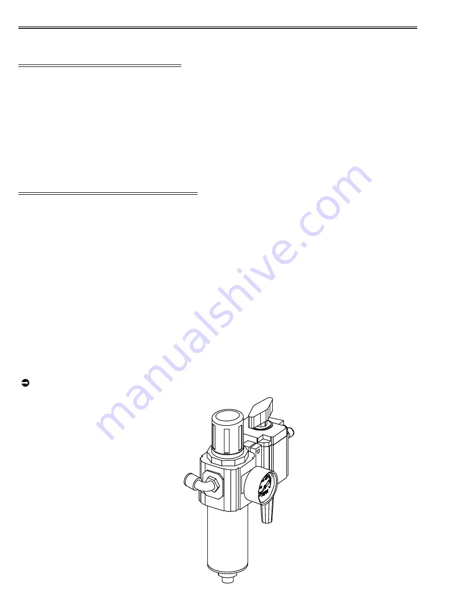
The saw must be connected to a steady supply of compressed air. The incoming air supply is
connected to the Filter / Regulator. It is located on the right and toward the back of the machine.
See Figure 6 on the next page.
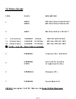
Verify that the power supply voltage corresponds to the voltage indicated on the specifications plate of
the machine. Connect the cable to the power supply, using a plug that is appropriate for the
characteristics of same, and complies with local and national electric codes.
Once the machine is connected, verify that the saw blade rotation is away from the operator when
the operator is standing in front of the machine. If the saw blade rotation is not correct, swap two
phases of the incoming power to the motor. Then, check the rotation again.
Summary of Contents for SUP-600-NF
Page 1: ...You have downloaded a manual for our MODEL SUP 600 NF PRECISION MITER UP CUT NON FERROUS SAW...
Page 3: ...www scotchman com SUP 600 NF SAW FIGURE 1 Page 2...
Page 9: ...2 4 Cutting Capacity FIGURE 3 Page 7...
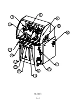
Page 16: ...FIGURE 8 1 2 3 4 5 6 7 9 10 14 13 12 11 Page 14 8 15...
Page 20: ...FIGURE 10 Filter Regulator Lubricator has a 1 4 BSPT Thread Page 18...
Page 26: ...Page 24 FIGURE 13 19 P N 677 LEGEND PLATE 1...
Page 40: ...Page 38 FIGURE 20 14 13 12 11 10 9 8 7 6 15 1 2 5 4 3...
Page 44: ...Page 42 FIGURE 23...


