background image

5. INSTRUCTIONS FOR USE

5.1 Proper and Improper Use

This is a semiautomatic cut-off machine especially designed for cutting non-ferrous profiles. The use

of the machine for cutting other materials is hereby prohibited. Such use may cause damage to the

machine and put the health and safety of the worker at risk.

5.2 Function of the Operating Mechanisms

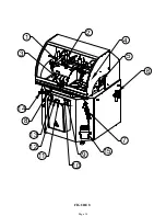
1. Horizontal clamps

2. Vertical clamps

3. Lever turn disc

4. Protective shield

5. M-10 x 40 lever

6. reg manometer

7. Clearing gun with hose

8. Advanced regulator 3/8"

9. Raise blade, green button

10. Two position selector

11. Green indicator light

12. Saw blade on-off

13. Emergency stop

14. Pressure regulator for horizontal clamps set at 2-3 Bar


DANGER: Always work with the protective shield lowered.


DO NOT DISCONNECT ANY SAFETY DEVICES!

NOTE:  The clamping cylinders should not be used with the rod completely extended. The stress
produced when the rod of the cylinder is extended completely will reduce the life of the cylinder.
It should be at a distance of 1-1/4" to 1-1/2" (30-40 mm) from the material that's being clamped.

Page 13

DANGER: We are not responsible for any possible accident caused by

                    the failure to comply with the aforementioned provision.

15. Coolant reservoir.

Summary of Contents for SUP-600-NF

Page 1: ...You have downloaded a manual for our MODEL SUP 600 NF PRECISION MITER UP CUT NON FERROUS SAW...

Page 2: ...PRINTED MAY 2021 www scotchman com SCOTCHMAN INDS 180 E US HWY 14 PO BOX 850 PHILIP SD 57567 Call 1 605 859 2542 MODEL SUP 600 NF COLD SAW...

Page 3: ...www scotchman com SUP 600 NF SAW FIGURE 1 Page 2...

Page 4: ...ORKERS CIRCULAR COLD SAWS DIGITAL PROGRAMMABLE FEED SYSTEMS SU 280 G BAND SAW 66 to 176 TON PRESSPRO HYDRAULIC PRESSES SCOTCHMAN INDS 180 E US HWY 14 PO BOX 850 PHILIP SD 57567 Call Toll Free in USA 8...

Page 5: ...it Switching Power Circuit Operating Controls Pneumatic Schematic Cast Iron Table Disc Assembly Exploded View 3 0 4 1 4 2 4 0 4 3 4 4 4 5 4 7 5 1 5 0 5 2 5 3 5 4 6 1 6 2 6 0 6 3 7 1 7 0 7 2 7 3 7 4 7...

Page 6: ...ill within three years of the date of purchase replace F O B the factory or refund the purchase price for any goods which are defective in materials or workmanship provided the buyer at the seller s o...

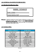
Page 7: ...AS WELL AS THE NAME OF THE PART AND THE PART NUMBER THAT APPEAR IN THE LAST CHAPTER OF THE PARTS EXPLODED VIEWS Motor speed Bore of blade Maximum of saw blade Miter Stops Presets Working pressure Pne...

Page 8: ...2 3 Dimensions of the Machine 64 3 8 41 1 2 51 1 4 41 5 16 35 5 8 Max Width 49 3 16 36 3 4 30 5 16 33 9 16 38 3 4 SAW BED 64 3 8 FIGURE 3 Page 6...

Page 9: ...2 4 Cutting Capacity FIGURE 3 Page 7...

Page 10: ...use individual hearing protection equipment 3 0 INSTRUCTIONS REGARDING TRANSPORT STORAGE Store in the vertical position Do not stack If the machine remains stored for a long period of time periodicall...

Page 11: ...The saw must be connected to a steady supply of compressed air The incoming air supply is connected to the Filter Regulator It is located on the right and toward the back of the machine See Figure 6...

Page 12: ...ew blade 4 Install the new blade and the blade flange and blade nut The saw blade rotates counter clockwise Page 10 when facing the blade from the left side of the machine The air inlet location is sh...

Page 13: ...is powered If the blade is not installed in the proper orientation the teeth will be dulled almost immediately 5 Close the access panel and reset the safety switch FIGURE 7 4 5 Cutting Coolant 3 1 2 I...

Page 14: ...e Once fully disengaged the door will be able to be opened 7 Before proceeding have a second person press and hold both green buttons on the control panel briefly to engage saw This should cause the s...

Page 15: ...egulator 3 8 9 Raise blade green button 10 Two position selector 11 Green indicator light 12 Saw blade on off 13 Emergency stop 14 Pressure regulator for horizontal clamps set at 2 3 Bar DANGER Always...

Page 16: ...FIGURE 8 1 2 3 4 5 6 7 9 10 14 13 12 11 Page 14 8 15...

Page 17: ...machine are not blocked that there are no damaged parts and that all machine components are positioned and working correctly NEVER operate the machine with any of the safety devices disabled or remov...

Page 18: ...ine may be damaged or the user may be injured 6 3 Manufacturer s Recommendations In the event that the machine is broken down or the saw blades must be replaced place a padlock on the protection switc...

Page 19: ...6A Side Drawer Cuttings M16 Feet Levelers 2040000092 Oleo Pneu Converter Left Door Pressure Regulator Protective Shield Support Protective Shield E00000BD25 B0000P1040 Hood Switch Turret M 10 x 40 Lev...

Page 20: ...FIGURE 10 Filter Regulator Lubricator has a 1 4 BSPT Thread Page 18...

Page 21: ...N 3 Current Motor 21690460M3 WITH Brake 5 5HP 230V 460V3PH Motor C2050000522 NO Brake 4KW Motor 3PH 460V 5 5HP 3B Old Style Motor 21690220M3 WITH Brake 4KW Motor 3PH 230V 5 5HP 3A Old Style Motor ITEM...

Page 22: ...I M1 U1 V1 W1 QM1 KM1 4kW III 460V 4kW III 230V 50 60 Hz 8A 14A 460V 8A 230V 14A 50VA 2A R S T PE 460 230 V 24V 24 0 124 1 2 3 4 5 6 7 MOTOR 4 Kw Contactor MAIN SW ITCH FUSE TRANSFORMER 50VA EMERGENC...

Page 23: ...12 Blade ON OFF Switch Operator Only KPM Coil 24VAC High Low Pneumatic DILM 12 10 24VAC Contact Magnetic Sensor Power Hood Omron Relay SUP500 SUP600 562023 2 Pos Sel without RazorGage 2 Pos Sel with...

Page 24: ...AMPS SHIELD LATERAL DOOR REAR DOOR START STOP BLADE KM1 MAX MIN PRESURE 5B 0 124 24 0 R1 15 17 5 16 LOWER BLADE R1 EQ4 16 13 9 8 OPEN SHIELD RELAY OF RAISE AUTOMATIC SWITCHING POWER CIRCUIT SHIELD 17...

Page 25: ...red symbol I Off red O 12 Push buttons for raising the saw blade 18 Auto manual selector for the pneumatic protective shield operation optional 8A 8 011877 Selector Switch Hold down clamp WITH OUT Raz...

Page 26: ...Page 24 FIGURE 13 19 P N 677 LEGEND PLATE 1...

Page 27: ...ssure Regulator 1 4 Horiz Clamps 40 x 320 Mini Ball Valve 1 8 M H Flow Regulation 1 8 6 CIL Quick Exhaust Valve 1 8 Uni Directional Valve Holddown Clamp 45MM Blow Air Duster Oleo Pneumatic Converter A...

Page 28: ...Page 26 FIGURE 14 13 18 13 12 17 11 14 10 10 11 15 16 01 02 03 05 04 06 07 06 07 08 09 00 EQ4 EQ2 EQ1 EQ3 POWER HOOD 4 2 5 1 19...

Page 29: ...N000000025 B000000011 2040000482 230110 221120 216000F012 201230 2160000CG2 2160000022 1724 M12 DIN127 Lock Washer M12 X 50MM DIN912 SHCS Autolubricated Tip 30 35 35 ISO 50 Cyl Yoke ISO 50 Cyl Yoke M...

Page 30: ...Page 28 FIGURE 15 28 27 26 25 24 23 22 21 20 19 18 17 16 15 14 29 13 12 11 10 9 9 8 7 6 5 4 3 2 1...

Page 31: ...r 60 Separator FAG 4206 BB TVH Bearing Rocker Shaft Pulley 1092 J12 Poly V Belt 40 X 10 X 6MM Washer M10 DIN127 Lock Washer M10 X 25MM DIN933 HHCS DIN913 M8 x 16 Screw Connecting Rod Pin 45x7 Avell M...

Page 32: ...METER ROD Insert in Blade Washer hole to hold spindle when changing blades 14 29 13 12 11 10 9 8 7 6 5 4 3 2 1 28 27 26 25 24 23 22 21 20 19 18 17 16 15 30 31 32 33 34 35 073420 M8x16 073420 M8x16 073...

Page 33: ...00P1060 N02PT14050 TD93310040 214012 208012 B0000000H2 214012 1808 073626 2350000131 073420 Aluminum Holder 45MM DIA 45 X 12MM Washer M12 X 50MM Adjustment Handle Holddown Clamp 45MM Uni Direc Valve M...

Page 34: ...FIGURE 17 14 29 13 12 11 10 9 9 8 7 6 5 4 3 2 1 28 27 26 25 24 23 22 21 20 19 18 17 16 15 30 31 32 Page 32...

Page 35: ...X 10 DIN912 SHCS D912 M 14 x 40 Screw Adaptor 1 4 8 Filter Regulator Manometer 1 8 BSPT Gauge 160 PSI M5 X 20MM DIN912 SHCS M5 DIN127B Lock Washer Male Stud Elbow 1 4 8 Advance Regulator 3 8 Cleaning...

Page 36: ...Page 34 FIGURE 18 14 29 13 12 11 10 9 8 7 6 28 27 26 25 24 23 22 21 20 19 16 15 30 32 1 2 5 4 3 17 18 33 34 35 36 37 38 39 40 41 42 43 44 45 47 46 31...

Page 37: ...Nut DIN934 Right Protective Shield ISO 7380 M6 x 12 BHCS ISO 7380 M8 x 12 BHCS Final Guide of End of Travel 204000A401 TD79910840 214011 215013 20400TB452 E00000BD25 073619 73206 20400TB452 4884 Conne...

Page 38: ...Page 36 FIGURE 19 14 29 13 12 11 10 9 8 7 6 28 27 26 25 24 23 22 21 20 19 16 15 30 1 2 5 4 3 17 18 31...

Page 39: ...14 DESCRIPTION DIN 471 12 ISO 40 Pin M6 Nut DIN934 M6 X 20 ISO 7380 BHSCS 90 Swivel Flange ISO 40 M8 x 25 Screw DIN 912 ISO 40 Swivel Flange DIN 471 12 ISO 50 x 200 Cylinder SUP 600 M10 DIN439 Jam Nut...

Page 40: ...Page 38 FIGURE 20 14 13 12 11 10 9 8 7 6 15 1 2 5 4 3...

Page 41: ...LLOW GREEN BLACK RED ENCODER 21 22 COUNTER R2 PULSE COUNTER CONNECTION 124 24 124 124 24 1 EQ1 EQ3 EQ2 11 124 3 5 12 13 KM1 14 6 126 7 125 8 13 9 10 10 11 14 15 OPEN CLAMPS BLADE ROTATION BLADE UP CLA...

Page 42: ...reads 00090 00 Press and hold the F key for 3 seconds until the screen reads an angle Press and hold both the F key and the Set key until the screen reads 90 00 NOTE This is a battery operated readou...

Page 43: ...3 NO on the Auxiliary Contact 3 Attach a Brown Jumper Wire from 34 NO on the Auxiliary Contact to the bottom of the terminal strip where the 124 wire is 4 Attach the Blue Wire to the top of the Ground...

Page 44: ...Page 42 FIGURE 23...

Reviews: