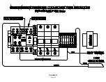
9.0 ANGLEMASTER W/CHIP COLLECTOR WIRE LOCATIONS
TO MAKE THE CHIP COLLECTOR START WITH THE ANGLEMASTER, READ THE BELOW
AND USE THE WIRE LOCATIONS DRAWING ON THE FOLLOWING PAGE.
1. Attach the Auxiliary Contact (P/N 011981) to the top of the saw contactor.
2. Attach the Brown Wire from the Chip Collector to the #33 NO on the Auxiliary Contact.
3. Attach a Brown Jumper Wire from #34 NO on the Auxiliary Contact to the bottom of the terminal
strip where the #124 wire is.
4. Attach the Blue Wire to the top of the Ground Terminal on the right end. The Ground Terminal is
yellow and green.
5. It should now be able to run with the Remote Setting on the Chip Collector.
These are instructions on how to wire the Chip Collector
(P/N 829230 - 230V 3PH or P/N 829460 - 460V 3PH)
to our SUP-500 or SUP-600 NF Upcut Anglemaster saws.
Page 41
Summary of Contents for SUP-600-NF
Page 1: ...You have downloaded a manual for our MODEL SUP 600 NF PRECISION MITER UP CUT NON FERROUS SAW...
Page 3: ...www scotchman com SUP 600 NF SAW FIGURE 1 Page 2...
Page 9: ...2 4 Cutting Capacity FIGURE 3 Page 7...
Page 16: ...FIGURE 8 1 2 3 4 5 6 7 9 10 14 13 12 11 Page 14 8 15...
Page 20: ...FIGURE 10 Filter Regulator Lubricator has a 1 4 BSPT Thread Page 18...
Page 26: ...Page 24 FIGURE 13 19 P N 677 LEGEND PLATE 1...
Page 40: ...Page 38 FIGURE 20 14 13 12 11 10 9 8 7 6 15 1 2 5 4 3...
Page 44: ...Page 42 FIGURE 23...

