background image

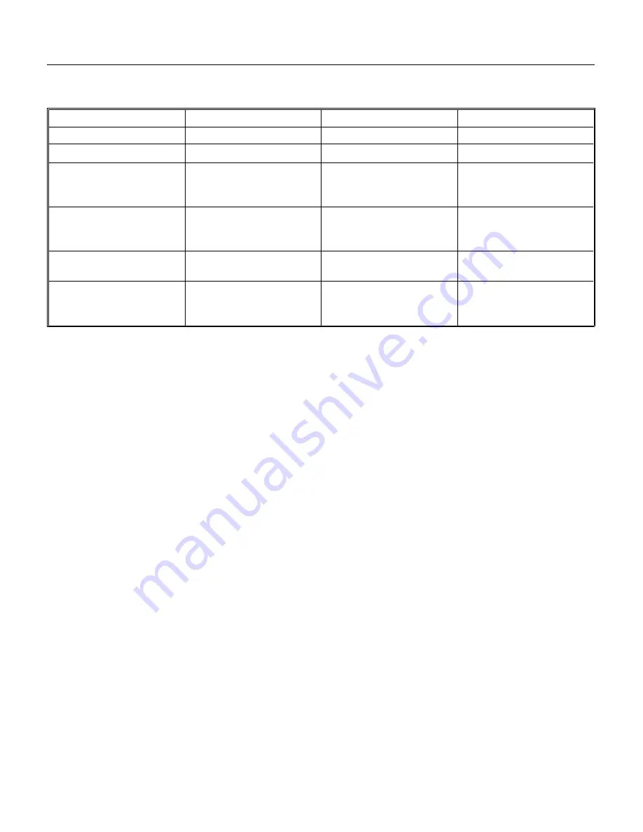
SYSTEM SPECIFICATIONS: CME1402

The following numbers are a guideline to field operation. There will be some variation from unit to unit.

The numbers heading the columns are: Condenser air temp./Cabinet air temp./Water temp.

Typical Harvest Ice Weight

••

13.5 to 14.5 lb.

Refrigerant Charge: 

••

 336 ounces of R-404A when connected to a MAC 7G condenser

••

448 ounces of R-404A when connected to a RCE1401 condenser

••

448 ounces of R-404A when connected to a ERC401 condenser.

Typical Compressor Amp Draw

Single phase

••

5 minutes into freeze:  15 - 16  Harvest:  22 - 23

Three phase

••

5 minutes into freeze:  9 - 10    Harvest:  13 - 14

High Pressure Cut Out

••

High pressure safety, Manual reset, cut out at 450 PSIG

Ice Level Control

••

Maximum Range = 8 feet

••

Partial Fill Setting = 21" - 22" from the base of the ice machine

Timer

••

1 revolution takes 10 minutes (changed from 8 in June 1996)

Cube Size Control

••

Cut In adjustable between 0

o

F. and +25

0

F.

0/70/55

90/90/70

110/90/80

Typical Cycle Time

15 - 17 minutes

16 - 17 minutes

18 - 19 minutes

Standard Harvest Time*

1

2

 minutes

1

2

 minutes

1

2

 minutes

Typical Freeze Cycle
Suction Pressure, End of
Cycle

35 PSIG

31-35 PSIG

36 PSIG

Typical Freeze Cycle
Discharge Pressure,
End of Cycle

265 PSIG

270 PSIG

310 PSIG

Typical Harvest Cycle
Suction Pressure, Peak

80 PSIG

90-95 PSIG

110 PSIG

Typical Air Cooled
Harvest Cycle Discharge
Pressure, Min

155 PSIG

180- 200 PSIG

235 PSIG

* See page 13 for harvest time optimization instructions.

CME1202R & CME1402R

June 1996

Page 22

Summary of Contents for CME1202

Page 1: ...age 12 FREEZING CYCLE OPERATION page 14 HARVEST CYCLE HOT GAS BYPASS page 15 COMPONENT DESCRIPTION page 16 CLEANING page 19 SYSTEM SPECIFICATIONS CME1202 page 21 SYSTEM SPECIFICATIONS CME1402 page 22 ADJUSTMENTS page 23 SERVICE DIAGNOSIS Water page 24 SERVICE DIAGNOSIS Electrical and or Adjustments page 25 SERVICE DIAGNOSIS Refrigeration and or Mechanical page 26 SERVICE DIAGNOSIS Bin Ice Level Co...

Page 2: ...l Minimum Circuit Ampacity Maximum Fuse Size Refrigerant Charge R 404A Condenser Type CME1402RE 3A 48 x 243 8 x 271 2 208 230 60 3 15 5 20 336 oz Remote Air CME1402RE 32A 48 x 243 8 x 271 2 208 230 60 1 22 9 30 336 oz Remote Air CME1202RE 3A 48 x 243 8 x 271 2 208 230 60 3 14 4 20 336 oz Remote Air CME1202RE 32A 48 x 243 8 x 271 2 208 230 60 1 20 9 30 336 oz Remote Air CME1202RE 6A 48 x 243 8 x 27...

Page 3: ...BACK VIEW OF CABINET CME1202R CME1402R June 1996 Page 3 ...

Page 4: ...ERC401 SPECIFICATIONS 23 13 16 19 7 8 ERC Dimensions A B F G 43 3 8 10 3 4 21 3 4 16 5 8 CME1202R CME1402R June 1996 Page 4 ...

Page 5: ...nt to rear and side to side directions by adjusting the leg levelers 3 Inspect the bin top mounting gasket It must be flat with no gaps to provide a good water seal when the cuber is installed on top of the bin Ice Maker Install the modular cuber on top of the bin using care to be sure a good seal is made between the two cabinets Use of a mechanical lift is recommended Align the holes in the botto...

Page 6: ... gasket from the stacking kit to the top edge of the bottom ice machines evaporator compartment Install the panel retaining bracket onto the bottom ice machine before placing the upper unit on it Place additional gasket onto the top edges of the bottom ice machine Carefully lift the uncrated top unit onto the bottom one and align the two cabinets Use of a mechanical lift is recommended for this st...

Page 7: ... precharged refrigerant lines consists of a 3 8 inch diameter liquid line and a 1 2 inch diameter discharge line Both ends of each line have quick connect couplings the end without access valves goes to the ice maker Note The openings in the building ceiling or wall listed in the next step are the minimum sizes recommended for passing the refrigerant lines through REFRIGERANT CONNECTIONS TYPICAL I...

Page 8: ...line The 3 8 inch liquid line goes to the ice maker fitting marked liquid line Final Connections 3 Begin tightening the couplings together by hand then using two wrenches it is important that ONLY the nut on the precharged lines be turned the other parts of the couplings must NOT be allowed to turn or the process will tear out the diaphragms and they will be loose in the refrigeration system tight...

Page 9: ...esigned to be powered from the ice machine There is a separate electrical junction box at the back of the ice maker for the remote condenser Wire the remote condenser to the ice maker in accordance with local and national electric codes All outdoor wiring must be in rain proof conduit Note If connecting to another UL listed remote condenser follow the instuctions provided with that product for ele...

Page 10: ... best overall performance DRAIN Connections All drains are gravity type and must have a minimum of 1 4 inch fall per foot on horizontal runs The drains to be installed to conform with the local plumbing code Install a vertical open vent on drain line high point to insure good draining The ideal drain receptacle is a trapped and vented floor drain Recommended bin drain is 3 4 inch O D RIGID tubing ...

Page 11: ...Is the water supply line shut off valve installed and electrical wiring properly connected 9 Check all refrigerant lines and conduit lines to guard against vibration or rubbing and possible failure 10 Have the bin and cabinet been wiped clean 11 Has the Manufacturers Registration form been properly filled out Check for correct model and serial numbers from Serial nameplate then mail to the SCOTSMA...

Page 12: ...ntrol box is the shaft of the timer and switch assembly Rotate the shaft of the timer clockwise until the actuator arm on the microswitch drops off outer cam into cam slot See Front View of Timer 6 Move the ICE OFF WASH to the ICE position 7 Check the water fill cycle For several minutes the inlet water valve will be open and water will flow into the reservoir Near the end of the fill cycle water ...

Page 13: ...d water will result in faster ice making but require longer harvest cycles Do NOT adjust harvest time too short or the unit will not harvest all the ice The harvest time is set by loosening the set screw on the cam rotating the shaft to open or close the distance between the high part of the cams and re tightening the set screw More of an opening between the cams high areas more harvest time An ad...

Page 14: ...complete the electrical circuit to the timer The timer then controls the remainder of the freezing cycle The timer will keep the ice maker operating in the freezing cycle for a selected length of time This will give the ice cubes time to fully form after that selected length of time the timer will switch the ice maker into the harvest cycle through the contacts of the timer assembly microswitch Lo...

Page 15: ...ffect of the hot gas condensing in each evaporator plate and the water cascading over the ice cubes The released ice cubes drop into the ice storage bin below At the end of the harvest cycle the timer cam will push the actuator arm to the microswitch IN If the ice level control is still CLOSED a whole new cycle will begin If the ice level control is OPEN the ice maker will begin to shut OFF Pump D...

Page 16: ... Assembly The function of the timer begins when activated by the cube size control The outer surface or large diameter lobe of the timer cam determines the timer cycle for finish freezing of the ice cubes while the inner surface or small diameter lobe determines the time cycle for the harvest cycle When the microswitch button is pushed in there is power connected to the coil of the relay and the u...

Page 17: ...FULL it will not allow the machine to fill the bin any closer to the ice machine than about 8 and it will not work if the distance to the bottom of the bin is greater than 8 feet Because it uses sound waves a slight ticking sound can be heard coming from the bottom of the machine There are three parts to the control the transducer the circuit board and the ice level control switch FULL SOUND WAVES...

Page 18: ...istributor water flows to the cells of each side of the evaporator plates Gravity flow returns the unfrozen excess portion of water to the sump reservoir for recirculation Hot Gas Solenoid Valve The hot gas solenoid valve functions only during the harvest cycle to divert the hot discharge gas from the compressor by passing the condenser for direct flow in the evaporator plates to release ice cubes...

Page 19: ...s 10 Move the ICE OFF WASH switch to the OFF center position 11 Remove the cap and drain the cleaning solution from the sump Replace the drain cap 12 Rotate the shaft of the timer and switch assembly CLOCKWISE to the harvest position low part of the cam against microswitch Move the ICE OFF WASH switch to the ICE position to start the Harvest cycle If after completing this procedure one or more eva...

Page 20: ...ve scale 1 Mix a cleaning solution of 4 ounces of Scotsman Ice Machine Cleaner to 4 pints of hot 950 F to 1100 F water 2 Remove all ice from the bin 3 Using rubber gloves dip a nylon scouring pad into the cleaning solution and scrub the scale off of the liner 4 After the scale has been removed rinse all of the surfaces inside the bin with clean potable water To sanitize the bin and ice machine Fol...

Page 21: ...ssure safety Manual reset cut out at 450 PSIG Ice Level Control Maximum Range 8 feet Partial Fill Setting 21 22 from the base of the ice machine Timer 1 revolution takes 10 minutes changed from 8 in June 1996 Cube Size Control Cut In adjustable between 0o F and 250 F 0 70 55 90 90 70 110 90 80 Typical Cycle Time 16 17 minutes 17 18 minutes 19 20 minutes Standard Harvest Time 3 1 2 minutes 3 1 2 mi...

Page 22: ...re safety Manual reset cut out at 450 PSIG Ice Level Control Maximum Range 8 feet Partial Fill Setting 21 22 from the base of the ice machine Timer 1 revolution takes 10 minutes changed from 8 in June 1996 Cube Size Control Cut In adjustable between 0o F and 250 F 0 70 55 90 90 70 110 90 80 Typical Cycle Time 15 17 minutes 16 17 minutes 18 19 minutes Standard Harvest Time 3 1 2 minutes 3 1 2 minut...

Page 23: ...size control Rotating the shaft of the timer cam clockwise will allow putting the machine into either the freezing cycle or harvest cycle as required in the cleaning instructions To Adjust The Timer Switch Assembly The length of the harvest cycle can be changed by loosening the set screw on the cam and then rotating the shaft so that the opening between the cams change More of an opening between t...

Page 24: ... leaks through Replace inlet water valve See electrical adjustment See electrical adjustment Makes thick ice freezes up Water inlet valve restricted Clean or replace valve Low water pressure Check water filter or supply Sump covers out of position Re position sump covers Cubes too large Inlet water valve leaks through Replace inlet water valve See electrical adjustment See electrical adjustment Lo...

Page 25: ... valve Timer stuck Replace timer Relay does not energize unit stuck in harvest Replace relay Long freeze cycle Water inlet valve leaks through Replace inlet water valve Water temperature too high Advise user Cubes too small Cube size set wrong Adjust cube size Cubes size control stuck closed Replace cube size control Cubes too large Water inlet valve leaks through Replace inlet water valve and adj...

Page 26: ...igh in nameplate charge Hot gas valve leaks thru At the end of the freeze cycle there should be frost on the evaporator end of the hot gas tubes if not replace the hot gas valve Liquid and discharge lines are in contact with each other Separate and insulate them Unit shuts off before bin is full Bin Ice level control is set to Partial Move bin Ice level rocker switch to Full Compressor cycles on a...

Page 27: ...rmer If there is power go to D D Disconnect electrical power and test ice machine circuit by attaching a jumper wire between bin thermostat posts on circuit board part no 12 1912 01 the circuit board with the timer on it Reconnect power If machine does not start go back to machine circuit If machine starts disconnect electrical power remove jumper wire and reconnect electrical power Then go to E E...

Page 28: ... for the left water distributor tube and notch also that the distributor manifold connections at the top center of each evaporator plate is snug against the top of the plate Cube Size Control To remove the cube size control 1 Remove front panel 2 Remove cover from control box 3 Trace capillary tube from the cube size control to the refrigerant suction line 4 Remove the coiled capillary tube bulb f...

Page 29: ...o machine 2 Loosen and remove outlet water line from the inlet water solenoid valve assembly 3 Remove screws and pull the water solenoid valve out to gain access 4 Pull electrical cord from solenoid coil terminals 5 Remove inlet water fitting from the water solenoid valve To replace the inlet water valve assembly reverse the removal procedures Bin Ice Level Control Circuit Board 1 Disconnect Elect...

Page 30: ...ssor was warm throughout the replacement process the ice machine may be restarted without waiting to re warm the compressor Hot Gas or Liquid Line Valve 1 Before replacing this valve be certain that the valve is the cause of the problem 2 Remove the front panel 3 Discharge and recover the refrigerant 4 Unplug the coil of the valve 5 With the refrigeration system open unsweat the valve from the tub...

Page 31: ...o use the access valves Remove the cap from the stem use a 3 16 allen wrench to check that the valve is CLOSED The remove the core cap Close the valve and replace the caps when the job is finished The valve must be closed and the caps must be on or the valve will leak General Information Work on the refrigeration system should only be done when it is certain that the system needs repair Refrain fr...

Page 32: ...e manifold valve Note If all of the charge will not go in the discharge side A Shut the discharge access valve at the ice machine B Switch the machine on C Open the low side access valve at the ice machine D Open the low side manifold valve and observe the sight glass to be certain that only gas is flowing into the system E When the proper charge is indicated on the scale shut off the manifold val...

Reviews: