background image

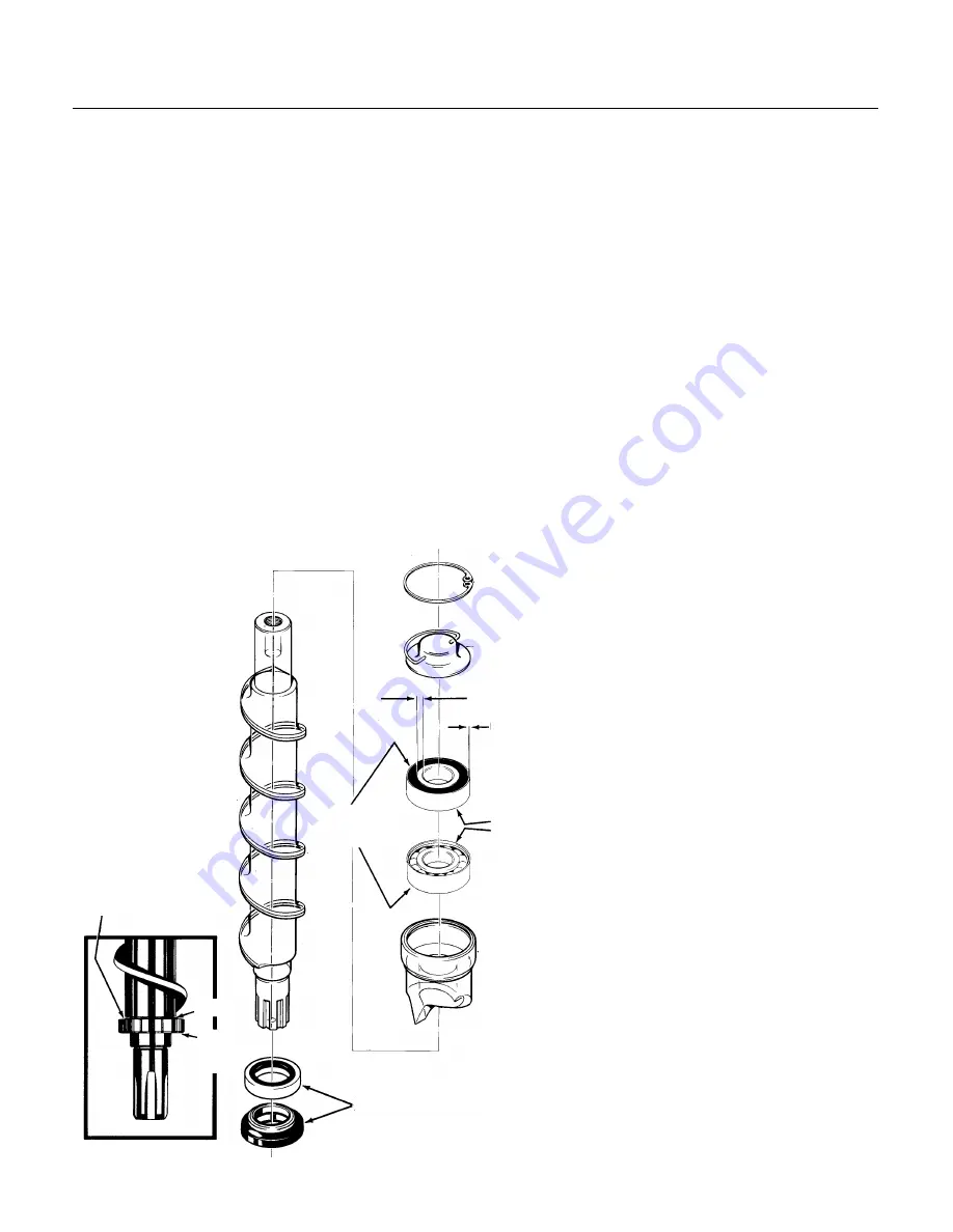
Inspection: Auger

The auger is made of stainless steel. It has a
polished surface that may be either shinny or dull,
but must be smooth. After removal, allow the auger
to dry to inspect for scale. If mineral scale is found
on the auger’s surface, clean off the auger with ice
machine cleaner and a scrubbing pad. 

Remove the water seal and clean off the shoulder
of the auger.

Bearings: The top bearing should spin freely with
no rough spots. If it feels rough when spun by
hand, replace it. There should be minimal rust or
dirt. If in doubt, replace the bearing.

Note: The top bearing used in the FDE470 is a
"directional" bearing. Note which way the inner
race is configured and install into the breaker. The
breaker is also available as a replacement part
with the top bearing already installed.

The bottom bearing must be removed from the
evaporator when replacing the water seal.

Remove bin cover.

To replace the water seal:

1. Remove old rotating half from the auger. Clean
the mounting area.

2. Place a bead of food grade sealant (such as
Scotsman part number 19-0529-01) onto the
shoulder of the auger where the rotating half of the
water seal will be installed.

3. Wash the new seal in water. While wet, slip it
onto the bottom of the auger, rubber side toward
the auger. Push up until seated against the
sealant. Do not allow any sealant to come into
contact with the face of the seal.

4. Wash the stationary half the water seal with
water. Slip it up into the bottom of the evaporator
until the bottom of the seal is inside the evaporator
about 1/4".

5. Push the bottom bearing against the water seal
until the bottom bearing is inside the evaporator
about 1/16".

6. Replace the evaporator on the adapter, and

re-attach the stand using the original bolts.

7. Attach the auger to the top bearing
and breaker.

8. Return the auger to the evaporator
and slide it down until the splines touch
the coupling.

9. Rotate the auger until the coupling
splines align with the auger.

10. Push the auger down, and rotate
the breaker until the screw holes line
up with the pilot holes in the evaporator.

11. When the auger is completely
seated, reinstall the breaker screws.

12. Replace permagum and foam top.

13. Switch on the water supply.

14. Check bin cover for electrical
grounds and switch on the electrical
power.

15. Observe operation. The unit should
make minimal noise while producing
ice. Catch first 2 minutes of ice and
discard it.

16. Replace the bin cover and all
panels.

Sealant

Here

Water Seal

Open

Sides

Inner Race

Wider on Top

Side

Outer

Race

Rubber

Smooth

Side

Remove the three bolts holding the
evaporator to the gear motor adapter and lift
the evaporator up
slightly. Tap the water
seal and bottom
bearing out from the
top down. Check the
bottom bearing the
same way as the top. 

Replace the water
seal and install a
new bearing set if
needed. 

FDE470

August 1994

Page 16

Summary of Contents for FDE470

Page 1: ...ice into the spout Table of Contents Specifications Page 2 To The Installer Page 3 For The Electrician Page 4 For The Plumber Page 5 Optional Kits Page 6 Wall Mount Kit KWB1 Page 7 Final Check List Initial Start Up Page 8 User Operation Page 9 Component Location Function Page 10 Refrigeration System Operation Page 11 Water System Operation Page 12 Mechanical Operation Page 13 Maintenance Page 14 A...

Page 2: ...nditions constitutes misuse and voids the warranty Scotsman Ice Systems are designed and manufactured with the highest regard for safety and performance They meet or exceed the standards of UL NSF and CSA Scotsman assumes no liability or responsibility of any kind for products manufactured by Scotsman that have been altered in any way including the use of parts and of other components not specific...

Page 3: ...are part of the water and have to be treated A water filter is always a good idea but does require regular maintenance to change the cartridge In some water conditions water treatment may be required Generally this means a polyphosphate feeder of some kind Water softeners are not recommended for the FDE470 General Installation Place the machine in its final location Remove the top right and left s...

Page 4: ...licensed electrician may be required in some situations Remove the back panel to make the electrical connection The electrical connection is made on the terminal strip in the junction box inside the machine Replace the back panel when the electrical connections are complete FOLLOW ALL APPLICABLE LOCAL STATE AND NATIONAL CODES This Unit MUST BE GROUNDED Electrical Power Remove Back Panel To Expose ...

Page 5: ...he bin drain a 5 8 plastic tube Install rigid tubing between the machine and the building drain Route the drains separately to the building drain Water supply Connect cold potable water to the machine A hand valve near the location is recommended A water filter is also a good idea Follow all local codes FOLLOW ALL APPLICABLE LOCAL STATE AND NATIONAL CODES Strainer or Filter Water Inlet Fitting Ins...

Page 6: ...unt the dispenser on the base The flange of the dispenser base fits in slots provided in the base extension Secure the base extension to the sink with the 3 screws on the front side panel 7 Mount the sink in place and secure with two machine screws 8 Install splash plate to cabinet with four machine screws The splash plate fits over the sink 9 Install the glass filler lever and holder to the splas...

Page 7: ...et 3 Drill out the holes as marked in the illustration in the back of the frame with a 3 16 drill bit 4 Place top hanger bracket on the inside of the frame and fasten to the frame with the four screws removed in step 2 Top Wall Bracket 1 Hold the bracket on the wall where it will be mounted 2 Mark on the wall the positions of the holes in the bracket 3 If needed drill pilot holes for the fasteners...

Page 8: ...lectrical power After about 15 seconds the machine should start 6 Let the machine operate listen for any unusual noises If needed reposition tubing panels to eliminate vibration After the unit has been operating for about 10 minutes there should be enough ice in the bin to test the dispense system 7 Using a container push the glass filler lever in and see that ice is dispensed the bin drive motor ...

Page 9: ...k or a back up of ice in the spout will occur To Vend Ice and Water Switch the Water Switch to ON Push in the glass filler lever water and ice will be dispensed into the container below the spout Note The water is NOT cooled it is the same temperature as the building supply water Daily Maintenance Pour hot water into the sink to flush out any debris or build up Wipe the cabinet off wash the sink a...

Page 10: ...de the bin that causes the ice to be swept over the spout and dispensed The vane is rotated by a gear motor at the top of the bin Bin Cover The bin cover not only keeps dirt from the ice storage bin it also is the support for the dispense gear reducer and the location of the electric eye bin controls Condenser The FDE470 uses an air cooled condenser It blows air out away from the fan motor The hea...

Page 11: ...ssure cause the refrigerant to evaporate and absorb heat from the metal walls of the evaporator After the refrigerant has flowed thru the evaporator it goes back to the compressor thru the suction line as a low pressure vapor At the compressor the cycle is repeated The FDE470 uses a low side pressure control as a safety it will shut the system down if the suction pressure is too low for reliable o...

Page 12: ... there is a water seal This seal is the type that has a rotating half and a stationary half The area where the two seals touch are smooth flat surfaces When the auger is installed in the evaporator it forces the rotating half of the seal against the stationary half The stationary half is spring loaded and provides a firm pressure against the auger portion of the seal Evaporator Float Valve Bin and...

Page 13: ...l continue to operate for about 2 minutes to clear the evaporator of ice Water Control Because water is such an important requirement for making ice a water level sensor has been placed in the reservoir If the water supply to the machine should fail the water level sensor will send a signal to the control board to shut down the machine Refrigeration The refrigeration system uses a hermetic compres...

Page 14: ...le sanitizing solution may be obtained by mixing 1 ounce of household bleach with 2 gallons of clean warm 95o F 115o F water 13 Unplug or disconnect electrical power 14 Remove bin top pour in warm potable water to melt out any ice 15 Pull out the vane and bin bottom from the bin 16 Thoroughly wash the bin s interior bin top interior spout ice vane and bin bottom with the sanitizing solution Pour s...

Page 15: ...e water supply 3 Remove top panel 4 Remove right side panel 5 Drain the evaporator and reservoir 6 Remove foam cap on top of evaporator 7 Remove 2 permagum plugs from the side of the evaporator 8 Remove 2 screws screwheads were covered by the permagum 9 Pull up on the pull ring to remove the auger If it is difficult to pull A Remove the breaker cover by taking the snap ring out B Unscrew the auger...

Page 16: ...lant to come into contact with the face of the seal 4 Wash the stationary half the water seal with water Slip it up into the bottom of the evaporator until the bottom of the seal is inside the evaporator about 1 4 5 Push the bottom bearing against the water seal until the bottom bearing is inside the evaporator about 1 16 6 Replace the evaporator on the adapter and re attach the stand using the or...

Page 17: ...or The water level sensor may not shut the ice machine off when the reservoir goes dry if there is a film of mineral scale on the probe tip 1 Remove the top panel 2 Remove the reservoir cover 3 Pull the water level probe up and out of the reservoir 4 Carefully wipe the tip of the probe with a clean cloth Ice machine cleaner may be needed Note The tip is made of glass 5 Reinsert the water level sen...

Page 18: ...on Check refrigeration system Ice in bin but will not dispense Drive motor does not turn Vend switch does not close Check replace vend switch Dispense motor open Check replace dispense motor Dispense output shaft broken Check replace output shaft Ice in bin motor turns vane Ice jammed up Users held cup against dispense spout and jammed unit Advise owner manager to instruct users Bin bottom slot no...

Page 19: ...lenoid coil open Replace solenoid Vend switch open Replace switch Water turned off Restore water supply Water drips from spout Melting ice in chute Some water dripping is normal Water solenoid leaks thru Replace solenoid Ice jammed in spout Clear ice jam check for cause Ice will not stop dispensing Vend switch stuck closed Replace switch Water leaks from cabinet Evaporator water seal worn or crack...

Page 20: ...s to determine if the fault is at the water level sensor the electric eyes or in the circuit board The sensors cannot be ohmed or jumped out To use the Scotsman Circuit Tester 1 Disconnect the electrical power 2 Unplug the electric eyes marked photo trans and LED and water level sensor marked water sen from the control board 3 Plug the connecting wires from the tester into the circuit board 4 Reco...

Page 21: ... Motor 1 Disconnect electrical power 2 Remove top panel 3 Remove one screw holding ground strap to cabinet frame 4 Cut off two dispense motor wire nuts 5 Remove screws holding dispense drive gear motor to the bin top 6 Pull gear motor off the bin top 7 Unscrew the output shaft extension from the gear motor 8 Remove screws holding the mounting bracket to the gear motor 9 Reverse to reassemble be ce...

Page 22: ...voir and lift the valve out of the reservoir tank 6 Replace with a new valve or replace the valve plunger Valve Plunger 1 After the valve has been removed from the reservoir remove the nut holding the valve to its mounting bracket 2 Pull out the cotter pin to release the internal valve plunger Note Do not replace the plunger if the valve s seat is damaged Replace the valve Inlet Water Valve 1 Disc...

Page 23: ...e bottom of the auger and force the auger up Do NOT damage the splines of the auger or the auger will have to be replaced If the auger is frozen to the bottom bearing do not force the bottom bearing thru the evaporator 1 Remove three cap screws holding evaporator to the adapter stand 2 Lift evaporator up slightly and tip the bottom out to expose the splined end of the auger 3 Remove snap ring hold...

Page 24: ...f the water seal with water Slip it up into the bottom of the evaporator until the bottom of the seal is inside the evaporator about 1 4 5 Push the bottom bearing against the water seal until the bottom bearing is inside the evaporator about 1 16 6 Replace the evaporator on the adapter and re attach the stand using the original bolts 7 Attach the auger to the top bearing and breaker 8 Return the a...

Page 25: ...alves must be in the closed position before the hose caps are removed Do not remove the hose caps before checking the position of the valve Use a 3 16 allen wrench to open and close the valve As with any other refrigerant do not place pressurized air or oxygen into the refrigeration system Note The refrigeration system uses an HFC type refrigerant and MUST use an HFC type drier Evacuation to 200 m...

Page 26: ...g the gear reducer to the cabinet frame 12 Trace auger drive motor wires back to the control box 13 Disconnect the drive motor wires from the relay on the circuit board 14 Pull the wires back to the auger drive motor 15 Pull the gear reducer out the side of the cabinet to remove it from the machine Note If there is evidence of water near the output shaft of the gear reducer it would be a wise prec...

Page 27: ...to a relay on the circuit board 2 Disconnect the auger motor s wires and pull them back to the auger drive motor 3 Lift the auger motor windings off the gear reducer If the rotor needs to be removed 1 Run a screw into the top of the rotor 2 Grasp the screw with a grip pliers 3 Pull and or tap on the pliers to pull the rotor bearing out of the gear reducer 4 Inspect the bearing and input seal Repla...

Page 28: ...FDE470 August 1994 Page 28 ...

Reviews: