Removal and Replacement
Panels:
1. Remove two screws at the back of the top panel.
2. Lift up at the back and push the top panel
forward to release it.
3. Remove 3 screws at the top, 3 screws at the
bottom and 1 screw at the front edge of each side
panel.
4. Push each side panel to the rear to release the
panel from the cabinet frame.
Dispensing System
The dispensing system consists of the vend switch,
dispense motor, dispense vane, bin bottom and
bin.
Vend Switch
1. Disconnect electrical power
2. Remove top panel
3. Remove right side panel.
4. Mark position of switch retaining screws in the
slots of the switch bracket.
5. Remove two screws holding vend switch to
mounting bracket.
6. Disconnect wires from vend switch
7. Remove switch from the machine.
8. Reverse to reassemble and install in the same
position as the original.
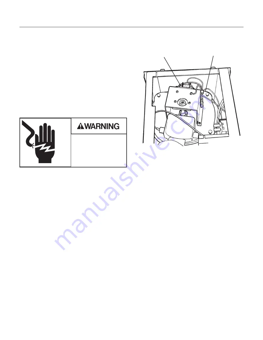
Dispense Gear Motor
1. Disconnect electrical power.
2. Remove top panel.
3. Remove one screw holding ground strap to
cabinet frame.
4. Cut off two dispense motor wire nuts.
5. Remove screws holding dispense drive gear
motor to the bin top.
6. Pull gear motor off the bin top.
7. Unscrew the output shaft extension from the
gear motor.
8. Remove screws holding the mounting bracket to
the gear motor.
9. Reverse to reassemble, be certain that the new
wire nuts are secure and that the ground strap is
reattached.
Dispense Vane
1. Disconnect electrical power.
2. Remove top panel.
3. Remove four thumb screws holding bin cover to
bin.
4. Lift bin cover off bin. Set aside.
5. Grasp the ice vane and pull it straight up.
6. Reverse to reassemble.
Bin Bottom.
Perform steps 1-5 above (to remove the dispense
vane).
1. Lift bin bottom out of the dispense bin.
2. When replacing, be sure that the slot on the bin
bottom is over the dispense chute (at the front).
FDE474
March 2000
Page 23
Dispense Drive
Motor
Bin Top
Electrical Shock Hazard
Disconnect electrical
power before beginning.


