Page 14
Page 14
freezing cycle with the start up of:
COMPRESSOR
WATER PUMP
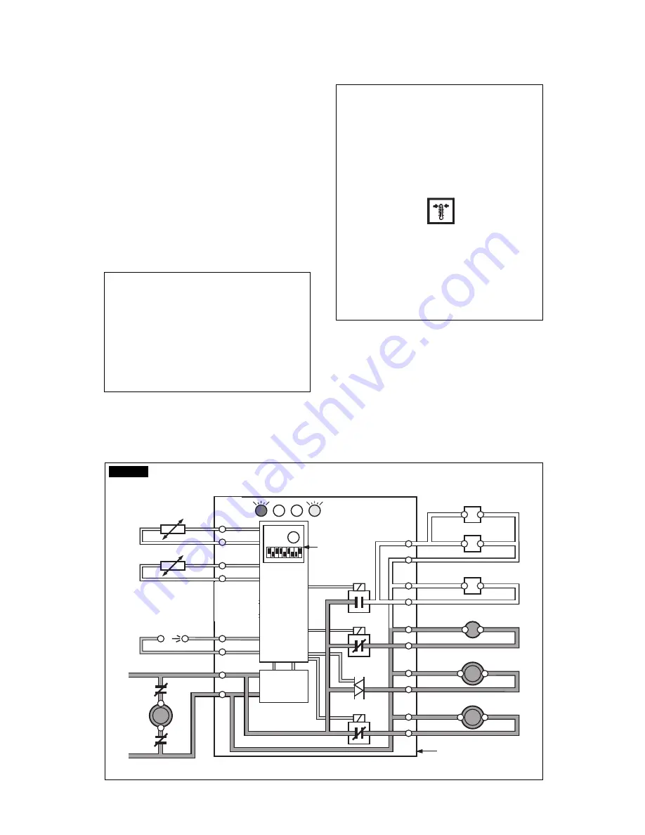
FAN MOTOR/S (in air cooled version) controlled
by the condensing temperature sensor located
within the condenser fins (Fig.2).
OPERATIONAL CHECKS
D.
If necessary install the refrigerant service
gauges on both the high side and low side
Schräder valves to check the compressor head
and suction pressures.
NOTE.
On air cooled models the condenser
temperature sensor, which is located within
the condenser fins, keep the head
(condensing) pressure between 16 and 18
bars (225-250 psig).
In the water cooled models the discharge
pressure is kept constant at the value of 17
bars (240 psig) by means of a water regulating
valve located on the water supply line to the
condenser.
In case of condenser clogging such to prevent
the proper flow of the cooling air or, in case
the fan motor is out of operation or shortage
of water in the water cooled condenser, the
condenser temperature rises and when it
reaches 70
°
C (160
°
F) - for air cooled version
- or 60
°
C (140
°
F) - for water cooled version -
the condenser temperature sensor shuts-off
the ice maker with the consequent light-up of
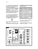
the RED WARNING LED (Fig.3).
After having diagnosed the reason of the rise
of temperature and removed its cause, it is
necessary to unplug (wait few seconds) and
plug in again the unit, thus to put the machine
in condition to initiate a new freezing cycle.
The machine restarts with the usual 5 minutes
water filling phase in order to provide enough
water into the sump tank.
E.
Check to see through the ice discharge
opening that the self propeller spray bar is correctly
rotating and that the water jets uniformely reach
the interior of the inverted mold cups and there is
not excessive water spilling through it.
16
15
14
13
2
1
7
8
9
10
3
4
5
6
11
12
Rx Tx
WATER IN VALVE
HOT GAS VALVE
CONTACTOR COIL
FAN MOTOR
WATER PUMP
- EVAPORATOR
- AMBIENT
- CONDENSER
TEMPERA
TURE SENSORS
BIN
COMPRESSOR
TRANSF.
D
ATA
PROCESSOR
ELECTR.
TIMER
DIP
SWITCH
ELECTRONIC CARD
L
N
RELAYS
RELAY
TRIAC
WATER DRAIN VALVE
FIG. 2
Summary of Contents for MC 15
Page 19: ...Page 19 Page 19 ...


