background image

3

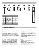
HARDWARE CONTENTS 

(NOT SHOWN ACTUAL SIZE) 

PART DESCRIPTION

QUANTITY

AA

25

Long Bolt

BB

Washer

25

CC

Wooden Dowel

18

Insert Bracket

DD

2

EE

Short Bolt

Touch-up Pen

6

FF

Screw

4

GG

1

SAFETY INFORMATION

AA

BB

CC

GG

DD

EE

FF

This device complies with Part 15 of the FCC 

rules. Operation is subject to the following two 

conditions:

Please read and understand this entire manual 

before attempting to assemble, operate or install 

the product.

This equipment has been tested and found to 

comply with the limits for Class B digital devices, 

pursuant to Part 15 of the FCC rules. These limits 

are designed to provide reasonable protection 

against harmful interference in a residential 

installation. The equipment generates, uses 

and can radiate radio frequency energy and, if 

not installed and used in accordance with the 

instructions, may cause harmful interference 

to radio or television reception, which can be 

determined by turning the equipment off and 

on. The user is encouraged to try and correct 

the interference by one or more of the following 

measures:

•   Reorient or relocate the receiving antenna

•   Increase the separation between the 

    equipment and the receiver

•   Connect the equipment into an outlet on a 

    circuit different from that to which the receiver 

    is connected.

•   Consult the dealer or an experienced radio/TV 

    technician for help.

1. This device may not cause harmful 

    interference, and 

2. This device must accept any interference 

    received, including interference that may 

    cause undesired operation.

Summary of Contents for 0839833

Page 1: ...ONS ITEM 0839833 0849091 0849092 Media Mantel with 28 IN Infrared Electric Fireplace TM Questions problems missing parts Before returning to your retailer call our customer service department at 1 855...

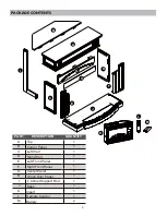
Page 2: ...TITY A Top Corner Panel 1 B 1 C Left Wall 1 D Right Wall Left Front Panel Right Front Panel 1 E 1 1 F G 1 H 1 I 1 Base J 1 K Insert 1 L Remote Control 1 M Battery 2 Wood Door Panel L Corner Support Ro...

Page 3: ...nterference in a residential installation The equipment generates uses and can radiate radio frequency energy and if not installed and used in accordance with the instructions may cause harmful interf...

Page 4: ...nsert or allow foreign objects to enter any ventilation or exhaust opening as this may cause an electric shock or re or damage the appliance This appliance has hot and arcing or sparking parts inside...

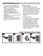
Page 5: ...his can cause the unit to overheat and could cause a fire A 15 Amp 120 volt 60 Hz circuit with a properly grounded outlet is required Preferably the replace will be on a dedicated circuit as other app...

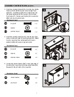
Page 6: ...three washers BB and three long bolts AA Repeat for right wall D From behind the assembly align the holes on left front panel E with the corresponding holes on left wall C securing with two washers B...

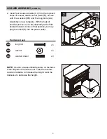
Page 7: ...left wall C and right wall D Attach top A securing from underneath with seven washers BB and seven long bolts AA 3 Insert two wooden dowels CC into the top middle holes on both left front panel E and...

Page 8: ...son position the insert K into opening of mantel assembly Note DO NOT plug the insert K into power outlet yet CAUTION DO NOT slide the insert on top of wood to avoid scratching wood surface 7 Secure t...

Page 9: ...five washers BB and five long bolts AA Assembly is now complete With the help of another person move the assembly to the final desired location Once in final position you may plug the insert K into t...

Page 10: ...de of the flip down door Start at a corner and pull to remove the four pieces Be careful not to damage the silicone trim as it will be used to secure the new panel 2 Remove the glass panel from the do...

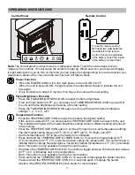
Page 11: ...and hold the TEMPERATURE TIMER ICON for 5 seconds to toggle between 5 F 3 C increments and 1 F 1 C increments when setting the temperature The unit will beep to indicate that the change has taken pla...

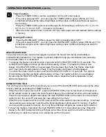
Page 12: ...then go blank while beeping 3 times The heater function is now engaged By pressing the HEATER ICON again you will be able to adjust the heat temperature to your desired temperature Press the DOWNLIGHT...

Page 13: ...he remote control L 2 Remove battery cover from the back of remote control L and remove the old batteries 3 Insert 2pcs AAA batteries ensuring the polarities of the battery match the inside of the bat...

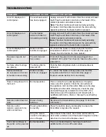
Page 14: ...r functions will work normally excluding the heater Until the problem is solved the error will only appear sound when the heater button is pressed Unplug unit wait 15 20 minutes then the sensor will r...

Page 15: ...nding the wholesale price of the defective part s Any installation labor construction transportation or other related costs expenses arising from defective part s repair replacement or otherwise of sa...

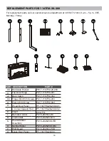
Page 16: ...PU17 1167FM 003 PU17 1167FM 004 PF 1167FM 28 200 001 PF 1167FM 28 200 002 Piston With Screw L Corner Support Rod M I Q I 16 Spinner Motor PU16 23262833 HB PCB Board PU16 262833 PCB Glass Door Panel PF...

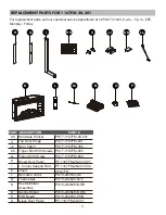
Page 17: ...001 PF 1167FM 28 201 002 Piston With Screw L Corner Support Rod M I 17 Spinner Motor PU16 23262833 HB PCB Board PU16 262833 PCB Glass Door Panel PF 1167FM 28 001 PU16 23262833 SM PU16 232628 NTC Remo...

Page 18: ...001 PF 1167FM 28 202 002 Piston With Screw L Corner Support Rod M I 18 Spinner Motor PU16 23262833 HB PCB Board PU16 262833 PCB Glass Door Panel PF 1167FM 28 001 PU16 23262833 SM PU16 232628 NTC Remo...

Page 19: ...LE 0839833 0849091 0849092 TM Meuble multim dia avec chemin e lectrique infrarouge 28 IN Date d achat _______________________ Des questions des probl mes des pi ces manquantes Avant de retourner l art...

Page 20: ...QUANTIT A Dessus 1 B 1 C Cloison gauche 1 D Cloison droite 1 E 1 1 F G 1 H 1 I 1 Base J K Foyer encastrable 1 L T l commande 1 M Pile 2 Panneau de coin Panneau avant gauche Panneau avant droit Pannea...

Page 21: ...pas install et utilis conform ment aux instructions risque de provoquer des interf rences nuisibles lors de la r ception d missions de radio ou de t l vision il suffit pour le v rifier d allumer et d...

Page 22: ...autre article similaire Placez le cordon dans un endroit peu passant et o il ne pourra pas tre accroch N ins rez JAMAIS un objet quel qu il soit dans les ouvertures de ventilation ou de sortie d air...

Page 23: ...Unis aux codes locaux et au code national de l lectricit ANSI NFPA NO 70 Afin de pr venir les risques d incendie ne bloquez JAMAIS les ouvertures de ventilation ou de sortie d air de quelque fa on que...

Page 24: ...les BB et trois longs boulons AA R p tez pour le mur droit D parti de l arri re de l assemblage alignez les trous du panneau avant gauche E avec les trous correspondants du mur gauche C Fixez avec deu...

Page 25: ...Bois x 2 AA BB CC 4 3 G 5 1 BB CC AA FF GG K A BB CC AA 1 2 Support De L insertion x 2 DD Boulon Court x 6 EE R p tez pour le c t gauche de l insertion K QUINCAILLERIE UTILIS E 3 Ins rez deux chevill...

Page 26: ...ionnez le po le K dans l ouverture de l assemblage de la chemin e Note NE branchez PAS le po le K dans une prise d alimentation MISE EN GARDE NE glissez PAS le po le sur le dessus du bois pour viter d...

Page 27: ...ersonne d placez l assemblage vers l emplacement final voulu Une fois en position finale vous pouvez branchez le po le K dans la prise d alimentation AA BB CC B x 5 x 5 QUINCAILLERIE UTILIS E Boulon L...

Page 28: ...porte basculant vers le bas Commencez dans un coin et tirez pour enlever les quatre morceaux Faites attention de ne pas endommager la bordure de silicone car elle sera utilis e pour fixer le nouveau p...

Page 29: ...BRIGHTNESS pour allumer l unit et la luminosit de la flamme reprendra le dernier r glage Appuyez sur l IC NE LUMINOSIT DE LA FLAMME FLAME BRIGHTNESS une fois de plus pour d filer travers les r glages...

Page 30: ...ppuy de nouveau E3 appara tra et ensuite dispara tra La flamme la lumi re et le minuteur fonctionneront normalement Seulement le chauffage et le ventilateur sont d sactiv s Pour d verrouiller la fonct...

Page 31: ...mpartiment des piles est situ l arri re de la t l commande L 2 Retirez le couvert des piles de l arri re de la t l commande L puis retirez la vieille piles 3 Ins rez deux piles AAA en vous assurant qu...

Page 32: ...r le bouton du radiateur et ce jusqu ce que le probl me soit r solu Pour d verrouiller l appareil de chauffage appuyez et maintenez le bouton de temp rature enfonc pendant 10 secondes Voir page 30 sec...

Page 33: ...s Vous appuyez trop rapidement sur les boutons Replacer avec 2 piles AAA Voir page 31 pour plus d information Appuyez lentement et uniform ment sur les boutons afin de vous assurer que l metteur recon...

Page 34: ...tant que l achat a t effectu chez un fournisseur ou un revendeur autoris de l article La pr sente garantie est limit e la r paration ou au remplacement des pi ces qui pr sentent des d fauts de mat ria...

Page 35: ...M 28 200 002 Piston avec vis Tige de support de coin en L M I Moteur De La Roue PU16 23262833 HB Carte De Circuit Imprim PU16 262833 PCB Panneau De Porte En Verre PF 1167FM 28 001 PU16 23262833 SM Ens...

Page 36: ...M 28 201 002 Piston avec vis Tige de support de coin en L M I Moteur De La Roue PU16 23262833 HB Carte De Circuit Imprim PU16 262833 PCB Panneau De Porte En Verre PF 1167FM 28 001 PU16 23262833 SM PU1...

Page 37: ...001 PF 1167FM 28 202 002 Piston avec vis Tige de support de coin en L M I Moteur De La Roue PU16 23262833 HB Carte De Circuit Imprim PU16 262833 PCB Panneau De Porte En Verre PF 1167FM 28 001 PU16 232...

Page 38: ...202 INSTRUCCIONES DE ENSAMBLAJE CUIDADO Y USO ART CULO 0839833 0849091 0849092 TM Fecha de compra _______________________ Preguntas problemas piezas faltantes Antes de volver a la tienda llame a nuest...

Page 39: ...ANTIDAD A Cubierta 1 B 1 C Pared izquierda 1 D Pared derecha 1 E 1 1 F G 1 H 1 I 1 Base J K Accesorio 1 L Control remoto 1 M Pila 2 Panel de esquina Panel frontal izquierdo Panel frontal derecho Panel...

Page 40: ...r energ a de radiofrecuencia y si no se instala y usa de acuerdo con las instrucciones puede causar interferencia perjudicial a las comunicaciones de radio o televisi n la que se puede determinar al e...

Page 41: ...sticos Coloque el cable lejos de reas de tr fico y donde alguien no se pueda tropezar NO introduzca objetos extra os ni permita que estos entren en las aberturas de ventilaci n o escape ya que podr an...

Page 42: ...en la parte superior de la madera para evitar rayar la superficie de madera NO coloque ning n objeto sobre el inserto ni bloquee las entradas de aire ventilaciones ya que esto puede causar un sobrecal...

Page 43: ...F E 2 C D BB AA 1 BB CC AA C J 2 Inserte cuatro espigas de madera CC en los orificios del lado izquierdo exterior de la base J Coloque el ensamblaje del Paso 1 en la base J asegur ndolo con tres rold...

Page 44: ...AA BB CC 4 3 G 5 1 BB CC AA FF GG K A BB CC AA 1 2 5 ADITAMENTOS UTILIZADOS Soporte Del Inserto x 2 DD Perno Corto x 6 EE Localice el soporte del inserto DD en el lado derecho del inserto K asegur ndo...

Page 45: ...i n final deseada Una vez en posici n final puede conectar la pieza de inserci n K al tomacorriente 7 6 1 Por la parte posterior del ensamblaje fije la varilla de soporte de esquina L I aseg rela con...

Page 46: ...el ensamblaje a la ubicaci n final deseada Una vez en la posici n final puede conectar el inserto K en el tomacorriente AA BB CC B x 5 x 5 x 4 ADITAMENTOS UTILIZADOS Perno Largo Arandela Espiga De Mad...

Page 47: ...de vidrio en el interior de la puerta plegable Comience en una esquina y tire para retirar las cuatro piezas Tenga cuidado de no da ar el borde de silicona ya que se utilizar para asegurar el nuevo pa...

Page 48: ...MPERATURA durante 10 segundos para desactivar la funci n de calentador Mantenga presionado el CONO DE TEMPERATURA durante 10 segundos nuevamente para activar la funci n de calentador Consulte la secci...

Page 49: ...o el calentador y el ventilador se desactivan Para desbloquear la funci n de calentador mantenga presionado el bot n Temperature durante 10 segundos El s mbolo E3 se mostrar y luego se pondr en blanco...

Page 50: ...minarse en el punto de recolecci n apropiado para el reciclaje Si se asegura de que la bater a se elimine de forma correcta evitar posibles consecuencias negativas para el medio ambiente y la salud hu...

Page 51: ...r autom ticamente Vuelva a enchufar la unidad y encienda el calentador Si el problema persiste p ngase en contacto con Servicio al Cliente Nota Las dem s funciones operar n normalmente excepto por el...

Page 52: ...El motor del ventilador sigue soplando luego de que se apaga la unidad Utiliza el control remoto demasiado lejos o fuera de ngulo Presione los botones de manera lenta y firme para asegurarse de que e...

Page 53: ...eparaci n reemplazo piezas defectuosas u otra situaci n y el fabricante no asume ninguna responsabilidad por las mismas El fabricante podr bajo su criterio eximirse de toda obligaci n respecto de esta...

Page 54: ...samblaje Del Calentador soplador Control remoto Termostato N K L O P Q H L M N O P K JJ II KK LL Q I HH PIEZA PIEZA DESCRIPCI N PH17 1167FM 28 200 PU17 1167FM 001 PU17 1167FM 002 PU17 1167FM 003 PU17...

Page 55: ...ol remoto Termostato N K L O P Q H L M N O P K JJ II KK LL Q I HH PIEZA PIEZA DESCRIPCI N 55 PH17 1167FM 28 201 PU17 1167FM 001 PU17 1167FM 002 PU17 1167FM 003 PU17 1167FM 004 PF 1167FM 28 201 001 PF...

Page 56: ...ntrol remoto Termostato N K L O P Q H L M N O P K JJ II KK LL Q I HH PIEZA PIEZA DESCRIPCI N PH17 1167FM 28 202 PU17 1167FM 001 PU17 1167FM 002 PU17 1167FM 003 PU17 1167FM 004 PF 1167FM 28 202 001 PF...

Reviews: