PREPARATION
MOUNTING OPTIONS
10. To disconnect, turn all controls to the off position, then remove plug from outlet.
11.
WARNING:
Risk of Electric Shock – Connect this furnishing to a properly grounded outlet only. See
Grounding Instructions.
12. Keep the cord away from heated surfaces.
SAVE THESE INSTRUCTIONS
SAFETY INFORMATION
5
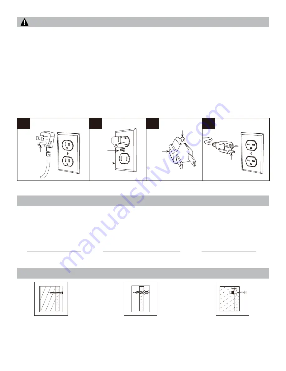
GROUNDING INSTRUCTIONS
This product is for use on 120 volts. The cord has a plug as shown below. See illustration for grounding
instruction. An adapter as shown at (C) is available for connecting three-blade grounding type plugs to
two slot receptacles. The green grounding lug extending from the adapter must be connected to a
permanent ground such as a properly grounded outlet box. The adapter should not be used if a three-slot
grounded receptacle is available.
WARNING:
Before beginning assembly of product, make sure all parts are present. Compare parts with
package contents list and hardware contents list. If any part is missing or damaged, do not attempt to
assemble the product.
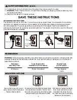
Secure main body (B) to wall
using screws (AA)(included) at
marked stud locations.
Screw wall anchors (BB)(included) flush
into desired wall location. Secure main
body (B) onto wall using provided screws
(AA)(included) into wall anchors (BB).
Drill holes at marked locations,
then insert wall anchors (not
included) into holes. Secure
the main body (B) to wall using
fasteners (not included).
Estimated
Assembly Time:
20 Minutes
Helpful Tools
(not included):
Tape Measure
Level
Tools Required for
Installation (not included):
Phillips Screwdriver
STUD WALL:
DRYWALL:
CONCRETE WALL:
(CONT’D)
A
B
C
D
Grounding Pin
Grounding Pin
Grounding Means
Metal
Screw
Cover of
Grounding
Box
Adapter


