Charge Station Overview
67
SCOTT SAFETY
087-0067 REV A
Cylinders Mounting
and Charging
This section covers mounting and charging the cylinders.
1
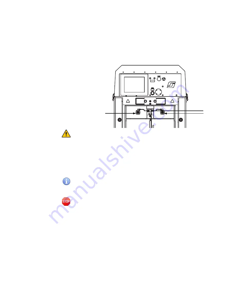
Close the Manual Air Flow On/Off Knob. Slowly open the bleed valve just enough
to vent any residual pressure. When all air stops escaping, hand-tighten the bleed
valve. Do not use tools to tighten. See
Figure 37
Bleed Value and Charge Adapters Locations
Caution: Never use a wrench or other tool to tighten the bleed valves or cylinder
adapters. Excessive force will damage the sealing surfaces and result in cylinder
leakage.
2
Remove one of the adapter caps and attach a cylinder to the charge adapter. Turn
counterclockwise to tighten. Hand-tighten the connector. Do not use tools to
tighten.
3
To charge two cylinders, remove the plug from the other charge adapter and mount
the second cylinder. Hand-tighten the charge adapter.
Never leave an unused charge adapter open. When charging only one cylinder, verify
that the cap is secure on the unused adapter.
4
Open the breathing air cylinder valves located on the top of the mounted cylinders.
Warning: Always open cylinder valves slowly. Careless handling of compressed air
can cause pressurized air to release suddenly, which can result in serious injury or
death.
5
Open the charging chamber door lock by operating the handle on the right side of
the chamber so that the Yellow lock bars are not showing.
6
Rotate the chamber door 180
°
until it clicks into position. See
1
2
2
Summary of Contents for HushAir Connect 7500
Page 1: ...User Guide 087 0067 Rev A HushAir Connect 7500 COMPRESSOR SYSTEM ...
Page 2: ......
Page 3: ...HushAir Connect 7500 User Guide COMPRESSOR SYSTEM 087 0067 Rev A ...
Page 8: ...IV CONTENTS 087 0067 REV A SCOTT SAFETY ...
Page 12: ...X LIST OF TABLES 087 0067 REV A SCOTT SAFETY ...
Page 42: ...20 CHAPTER 2 INSTALLATION 087 0067 REV A SCOTT SAFETY ...
Page 73: ...Configuring the System 51 SCOTT SAFETY 087 0067 REV A Figure 27 Override Status Screen ...
Page 106: ...84 CHAPTER 5 MAINTENANCE 087 0067 REV A SCOTT SAFETY Figure 48 Oil Drain Location 3 1 2 ...
Page 112: ...90 APPENDIX A SPECIFICATIONS 087 0067 REV A SCOTT SAFETY ...
Page 119: ......


