Page 16 of 44
P/N 595189-01 Rev A 4/10
regulAr oPerATionAl inSPecTion conTinued...
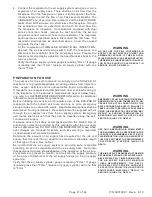
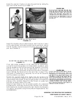
figure 7
COUPLING GASKET
PreSSure
reducing
regulATor
couPling
gASKeT
PRESSURE REDUCER AND AIR PATH INSPECTION
1. Inspect the gauge and ELECTRONIC alarm for damage or modi-
fications that may impair the intrinsic safety. Verify that a fresh
battery is installed in the ELECTRONIC alarm. The ELECTRONIC
alarm requires one 9V battery for operation. See the ELECTRONIC
ALARM BATTERY REPLACEMENT section of this instruction.
2. Inspect the pressure reducer for exterior damage.
3. Inspect the cylinder valve outlet threads and the coupling gasket.
The gasket is located on the nipple coupling that connects the
pressure reducer to the cylinder valve. To expose the threads and
the gasket for inspection, grasp the hand wheel coupling on the
pressure reducer and turn the hand wheel counterclockwise until
the pressure reducer separates from the cylinder valve. Inspect the
cylinder valve outlet for bent or damaged threads. If the gasket is
present and in good condition and the valve outlet is undamaged,
thread the coupling back onto the cylinder valve using hand tight
pressure. See FIGURE 7.
cAuTion
WrencheS ShAll noT be uSed To TighT-
en The hoSe couPling. over TighTen-
ing The hoSe couPling mAy dAmAge
The niPPle SeAl.
WArning
A dAmAged or miSSing couPling gAS-
KeT mAy cAuSe Air leAKAge ThAT mAy
reduce The durATion of uSe Which
could reSulT in circumSTAnceS
ThAT could cAuSe SeriouS inJury or
deATh.


