background image

Operating Machine - 12

OPERATING MACHINE

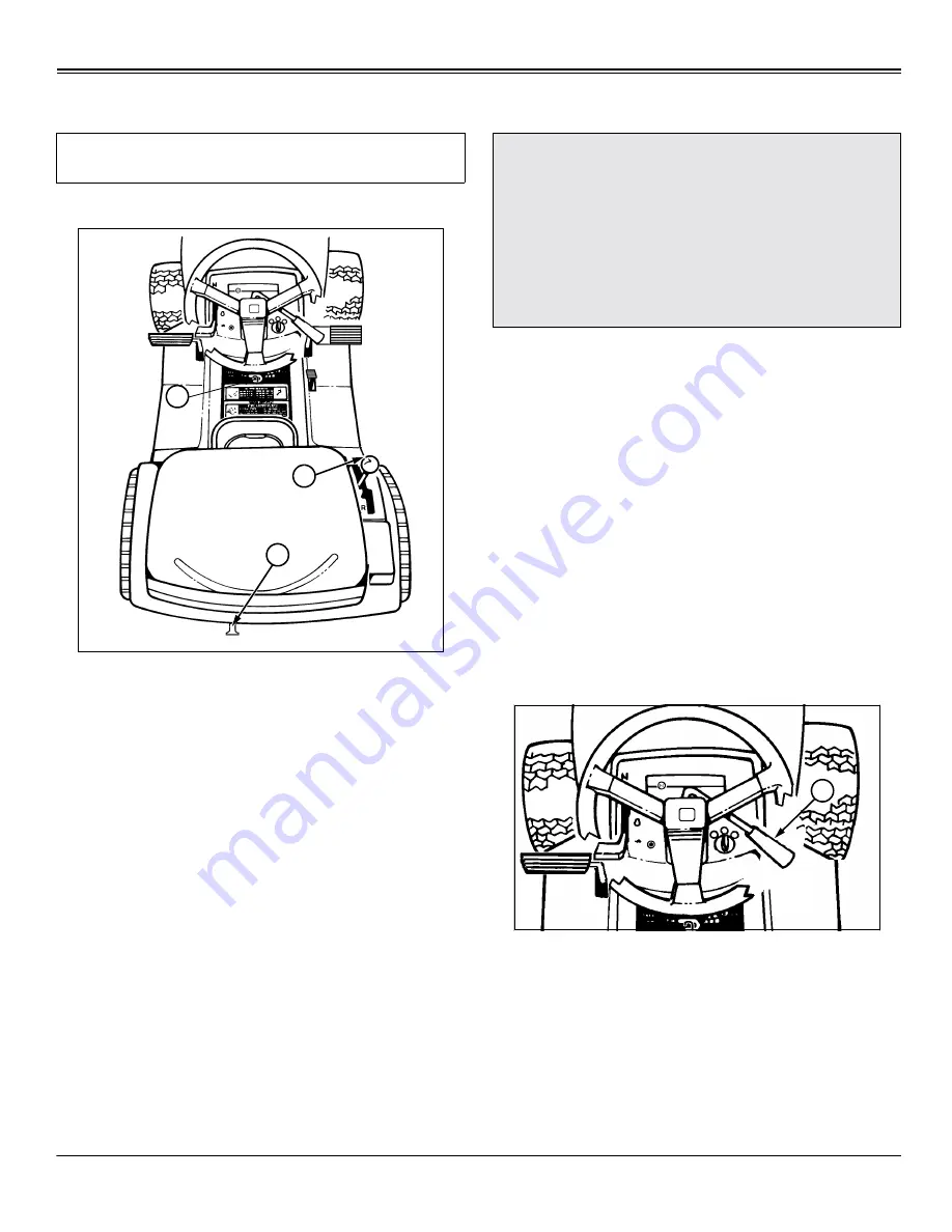
Pushing Machine

To move machine when engine is STOPPED:

Unlock the park brake (A).

GEAR MODEL: Put transmission shift lever (B) in N 

(Neutral).

AUTOMATIC MODEL: Pull out on free-wheeling lever 

(C).

Push machine to desired location.

NOTE: AUTOMATIC MODEL: Push free-wheeling lever 
(C) IN before operating tractor.

Daily Operating Checklist

Test safety systems.

Check tire pressure.

Check fuel level.

Check engine oil level.

Remove grass and debris from machine.

Testing Safety Systems

Use the following checkout procedure to check for normal 
operation of machine.

If there is a malfunction during one of these procedures, 
DO NOT operate machine. (See your Authorized Service 
Center for service.)

Perform these tests in a clear open area. Keep bystanders 
away.

NOTE: Your Lawn Tractor is equipped with a 
ELECTRONIC SAFETY INTERLOCK. Engine will not 
start unless: PTO lever is DISENGAGED. Brake pedal is 
depressed OR parking brake is set.

Test 1

1. Operator on seat.

2. Unlock the park brake.

3. Pull PTO lever (A) back to DISENGAGE.

4. Try to start engine.

5. Engine MUST NOT start. If engine starts, there is a 
problem with your safety interlock circuit. (See your 
Authorized Service Center.)

IMPORTANT: Avoid damage! Avoid transmission 
damage, DO NOT tow machine.

B

A

C

c

 CAUTION: Avoid injury! Engine exhaust fumes 

can cause sickness or death. 

If it is necessary to run an engine in an 

enclosed area, remove the exhaust fumes from 
the area with an exhaust pipe extension.

If you do not have an exhaust pipe extension, 

open the doors and get outside air into the 
area.

A

Summary of Contents for S1642, S1742, S2046

Page 1: ...OMGX10784 C0 C0 Scotts Lawn Tractors S1642 S1742 and S2046 OPERATOR S MANUAL North American Version Litho in U S A ...

Page 2: ... and maintain their equipment as described in this manual The product warranty is explained on the warranty certificate you received from your dealer Measurements in this manual are metric units and their U S customary equivalents RIGHT HAND and LEFT HAND sides are determined by facing in the direction the machine will travel when going forward When you see a broken line arrow it indicates the par...

Page 3: ...ocate the identification number for the machine and for the engine Record the information in the spaces provided below PRODUCT IDENTIFICATION NUMBER A under seat __ __ __ __ __ __ __ __ __ __ __ __ __ __ __ __ __ ENGINE SERIAL NUMBER B on fan shroud __ __ __ __ __ __ __ __ __ __ __ __ __ __ __ __ __ DATE OF PURCHASE _________________________________________ DEALER NAME ____________________________...

Page 4: ...tor mower deck is being set up for side discharger or 2 bag bagger DO NOT install mulch cover kit See Using Mower Deck Side Discharge OR Using Mower Deck with Optional Equipment in the Operating Mower section A Operator s Manual B Safety Video C Bag of Hardware D Key Bag of Hardware 2 M8x16 Bolts Battery 2 M8x16 Nuts Battery cCAUTION Avoid injury Prevent Battery Explosions Keep sparks lighted matc...

Page 5: ...ect tire pressure Do not inflate the tires above the recommended pressure Never weld or heat a wheel and tire assembly The heat can cause an increase in air pressure resulting in a tire explosion Welding can structurally weaken or deform the wheel When inflating tires use a clip on chuck and extension hose long enough to allow you to stand to one side and NOT in front of or over the tire assembly ...

Page 6: ... and while backing Never carry children even with blades off WARNING AVOID SERIOUS INJURY OR DEATH Drive up and down slopes not across Avoid sudden turns If machine stops going uphill stop blade and back down slowly Keep safety devices guards shields and switches in place and working Read operator s manual When leaving machine Stop engine Set park brake Remove key DANGER POISON SHIELD EYES EXPLOSI...

Page 7: ...certified with the United States Environmental Protection Agency EPA and or California Air Resources Board CARB The emissions warranty applies only to those engines marketed by John Deere that have been certified by the EPA and or CARB and used in the United States and Canada in off road mobile equipment Emission Compliance Period If your engine has the emission compliance category listed on the e...

Page 8: ...ob S2046 B Throttle Choke Control S1642 and S1742 Throttle Control S2046 C Foot Pedal Brake Clutch Return to Neutral D Reverse Implement Option Switch E Attachment Lift Lever F Locking Lever G Free Wheeling Knob H Transmission Shift Lever Hand Control Units Only Cruise Control Lever Foot Control Units Only I Park Brake J Foot Pedal Reverse Foot Control Units Only K Foot Pedal Forward Foot Control ...

Page 9: ...ugh to protect the operator and others from serious injury Park Safely Stop machine on a level surface not on a slope Disengage mower blades Lower attachments to the ground Engage park brake STOP engine Remove key Before you leave the operator s seat wait for engine and all moving parts to STOP Rotating Blades are Dangerous Protect Children and Prevent Accidents PROTECT CHILDREN Never assume that ...

Page 10: ...e by putting your foot on the ground Keep Riders Off Only allow the operator on the machine Keep riders off Riders on the machine or attachment may be struck by foreign objects or thrown off the machine causing serious injury Riders obstruct the operator s view resulting in the machine being operated in an unsafe manner Wear Appropriate Clothing Wear close fitting clothing and safety equipment app...

Page 11: ...edal Pedal should not return to the up position UNLOCKING PARK BRAKE 1 Push and hold foot pedal A all the way down 2 Move park brake lever B to the right then to the rear 3 Remove foot from pedal Pedal should return to the up position Starting Engine NOTE Engine will not start unless PTO lever is DISENGAGED park brake is LOCKED or brake clutch pedal is pushed down On GEAR model The transmission sh...

Page 12: ...d wait 10 seconds before cranking the engine again 7 Let engine run for a couple of minutes to warm up before operating tractor Using Throttle Control Always operate the engine at FULL r THROTTLE Operating the engine at less that full throttle reduces the battery charging rate and reduces fan cooling efficiency of the engine Full throttle offers the best bagging and mower performance Cold Weather ...

Page 13: ... pedal A all the way forward to the BRAKE position 2 Move shift lever B to the right and forward to desired FORWARD position 3 Slowly release foot pedal to engage machine drive TO TRAVEL IN REVERSE NOTE The engine and mower will stop as the shift lever is moved to the R REVERSE position with mower engaged 1 Push foot pedal A all the way down to STOP tractor 2 Pull PTO lever C all the way back to t...

Page 14: ...If cruise control is engaged move lever to OFF position Release either pedal B or C and unit will automatically return to neutral and STOP Push down on brake clutch pedal E Brakes will be applied to assist in stopping Using Cruise Control Use cruise control when you want to maintain travel speed without having to hold the forward travel pedal down Cruise control operates only for forward travel cC...

Page 15: ...o reposition the machine with the mower engaged 1 Stop the machine FORWARD travel with mower engaged On foot control models be sure cruise control lever is all the way rearward in the OFF position 2 Look behind the vehicle to be sure there are no bystanders 3 Push and hold in the reverse implement switch A while Automatic move drive lever to the rear or press reverse pedal Gear move the gear shift...

Page 16: ...rized Service Center for service Perform these tests in a clear open area Keep bystanders away NOTE Your Lawn Tractor is equipped with a ELECTRONIC SAFETY INTERLOCK Engine will not start unless PTO lever is DISENGAGED Brake pedal is depressed OR parking brake is set Test 1 1 Operator on seat 2 Unlock the park brake 3 Pull PTO lever A back to DISENGAGE 4 Try to start engine 5 Engine MUST NOT start ...

Page 17: ... speed position 7 Raise up off of seat DO NOT get off tractor 8 Engine will begin to stop If engine does not begin to stop there is a problem with your safety interlock circuit See your Authorized Service Center Test 4 1 Operator on seat 2 Push brake pedal down 3 Pull PTO lever A back to DISENGAGE 4 Put transmission shift lever B in N NEUTRAL position 5 Start engine and move throttle lever C to FA...

Page 18: ...utral On Automatic Models Pull out free wheeling lever C to unlock 3 Try to push machine manually 4 Park brake MUST prevent machine from moving If machine moves parking brake needs to be adjusted See your Authorized Service Center 5 On Automatic Models Push free wheeling lever back in Test 7 Test Reverse Implement Option 1 Start engine IMPORTANT Avoid damage On Automatic Transmission Models Do Not...

Page 19: ... grass bagger or dumpcart See your Authorized Service Center for Front Weights Remove front wheel weights when not required Using Rear Wheel Weights Use of rear wheel weights is recommended for improved traction when an attachment such as snowthrower or blade is used See your Authorized Service Center for Rear Weights Using Tire Chains Tire chains are recommended for use with snowthrower and under...

Page 20: ... the park brake Remove key Wait for mower blades to STOP Keep hands feet and clothing away from mower deck when engine is running DISENGAGE PTO lever to stop mower blades when you are not using mower Using Lift Lever to Raise and Lower Mower 1 Push down on lift lever A slightly and hold locking lever B down with thumb 2 Move lift lever A DOWN to LOWER mower or UP to RAISE mower 3 Release locking l...

Page 21: ...eling gauge Part Number TY15272 to aid in deck leveling may be obtained through your local Authorized Service Center at a nominal cost 1 Park tractor on a hard level surface 2 Stop engine and remove key 3 CHECK Tire pressures must be correct See Checking Tire Pressure in Service Miscellaneous section 4 Adjust cutting height to middle position 5 Turn left blade parallel to tractor axle Hold drive b...

Page 22: ...ades will cut grass twice and grass tips will turn brown 6 Turn nuts B on front draft rods C equally until adjustment is correct Turn nut clockwise to RAISE front of mower deck or counterclockwise to LOWER front of mower deck 7 Check front to rear deck measurements and readjust if necessary Engaging and Disengaging Mower Engaging Mower 1 START engine cCAUTION Avoid injury Before you adjust mower S...

Page 23: ...to Inspect or Unplug Mower or Optional Bagger 1 STOP machine 2 Pull PTO drive lever A back to DISENGAGE mower blades 3 Move throttle lever to SLOW t position 4 Lower mower to the ground 5 LOCK park brake 6 STOP engine 7 Remove key 8 Wait for all moving parts to STOP Using Mower Deck Side Discharge 42 Inch Mower Decks NOTE For maximum side discharge operation it may be necessary to change the mower...

Page 24: ... be installed 1 Install mulch cover Lift plastic discharge chute Grasp corner of steel chute pull outward to unlock and pivot up Install mulch cover into deck discharge opening and hook both rubber hooks B Using Mower Deck with Optional Equipment 42 Inch Mower Decks NOTE For maximum mower deck operation it may be necessary to change the mower blades see Servicing Mower Blades in the SERVICE MOWER ...

Page 25: ...Lift plastic discharge chute Grasp corner of steel chute pull outward to unlock and pivot up Unhook both rubber hooks B and remove mulch cover 2 Store mulch cover in a well protected area and have it readily available for when you want to use deck as a standard mulching deck ...

Page 26: ...part number TY 24747 Parts for S1642 Tractor Parts for S1742 Tractor Parts for S2046 Tractor Item Part Number Air Cleaner Elements Foam Paper M92360 Kohler 12 083 08 LG496894S Kohler 12 083 14 Fuel Filter AM38708 Oil Filter AM125424 Kohler 12 050 01 Battery TY21752 Spark Plug M78543 Champion RC12YC Fuse 15 amp 99M7065 Headlight Bulb AD2062R GE 1156 Ground Drive Belt GX10065 Item Part Number Air Cl...

Page 27: ...ct to change without notice Part Numbers may be different outside the U S A Item Part Number Blades Standard Bagger Mulch M139802 or M139803 M139803 M139802 Mower Drive Belts M124895 Leveling Gauge TY15272 Item Part Number Blades Standard Bagger Mulch M127466 N A M119232 Mower Drive Belts GX10176 Leveling Gauge TY15272 ...

Page 28: ...y impair its function and safety Wear Appropriate Clothing Wear close fitting clothing and safety equipment appropriate for the job Loud noise can cause impairment or loss of hearing wear a suitable protective device such as earplugs Do not wear radio or music headphones while servicing the machine Safe service requires your full attention Avoid Injury From Contacting Blades Before you unplug or a...

Page 29: ...ade belt tension After First 5 Hours Change engine oil Every 8 Hours Check oil level Check brakes Check tire pressure Every 25 Hours Sharpen replace blades Lubricate front wheel spindles Lubricate wheel bearings Check battery and clean battery terminals Change engine oil when operating under heavy load or in high temperatures Clean Service air cleaner elements Check spindle brake measurement Every...

Page 30: ...Service Interval Chart 26 SERVICE INTERVAL CHART Service Record DATE SERVICE PERFORMED ...

Page 31: ... still not performing correctly contact your John Deere dealer Avoid Fumes Engine Oil NOTE Air cooled engines run hotter than automobile engines The use of multi viscosity oil such as 10W 30 in ambient temperatures above 4 C 40 F will result in higher than normal oil consumption If multi viscosity oil used check oil level more frequently to prevent any possible damage due to lack of lubrication Us...

Page 32: ... If oil level is low add oil to bring oil level no higher than FULL on dipstick 9 Install and tighten dipstick Lower hood Changing Engine Oil and Filter 1 Run engine to warm oil 2 Park tractor on level surface STOP engine LOCK park brake and remove key 3 Lift hood 4 Put drain pan under drain valve 5 Unsnap the dust cap push and twist to open oil drain A and drain oil into oil drain pan 6 Close dra...

Page 33: ...oil level 16 If necessary add oil to bring level to FULL mark on dipstick Checking and Cleaning Air Cleaner Elements S1642 and S1742 NOTE It may be necessary to check the air filter more frequently if operating vehicle in dusty conditions 1 Lift hood 2 Clean any dirt and debris from the air cleaner before removing cover 3 Remove cover A 4 Inspect foam precleaner B and element C without removing 5 ...

Page 34: ...or air intake it MUST be remove 5 Lift out filter cartridge D and foam precleaner E 6 Service precleaner Wash precleaner in a solution of warm water and liquid detergent Rinse precleaner thoroughly Squeeze out excess water in a dry cloth until precleaner is completely dry Put approximately 30 ml 1 oz of clean engine oil IMPORTANT Avoid damage A damaged paper element C can allow dirt into the carbu...

Page 35: ...rk plug s if necessary 6 Check plug gap with a wire feeler gauge S1742 and S2046 Gap should be 0 76 mm 0 030 in S1642 Gap should be 1 02 mm 0 040 in 7 To change gap move the outer electrode 8 Install and tighten spark plug s If you have a torque wrench tighten plug s to 20 N m 15 lb ft 9 Connect the spark plug wire s 10 Lower hood Replacing Fuel Filter IMPORTANT Avoid damage A damaged cartridge D ...

Page 36: ...emove filter 6 Connect hoses to new filter 7 Install clamps and check for leaks 8 Lower hood Clean Air Intake Screen and Engine 1 STOP engine LOCK park brake and remove key 2 Lift hood 3 Clean air intake screen A and external engine areas B with rag brush vacuum or compressed air 4 Lower hood IMPORTANT Avoid damage To avoid overheating and damage to engine Keep air intake screen free of dust and d...

Page 37: ...and then full right turn to distribute grease in spindles Axle Pivot Lubricate axle pivot C with multipurpose EP grease or an equivalent Pivot axle up and down to distribute grease in pivot Drag Link Lubricate drag link D with multipurpose EP grease or an equivalent Pivot axle up and down to distribute grease in pivot Wheel Bearings S2046 Only Lubricate front wheel bearings B one on each side of t...

Page 38: ...des in Tighten the lock nut until the shim has slight interference Remove the shim and cycle the brake pedal Readjust if needed IF THE SHIM SLIDES FREELY Install the shim and tighten lock nut F until there is slight interference Remove the shim and cycle the brake pedal Readjust if needed Adjusting Brakes Automatic Hand Control 1 Park tractor on flat level surface STOP engine turn key to the OFF p...

Page 39: ...ime until specified measurements are obtained Brake lever F travel should not exceed 30 G If it does measure brake components individually SPECIFICATIONS Spring bracket to stop tabs minimum 2 mm 0 08 in Brake lever travel maximum 30 Adjusting Brakes Automatic Foot Control 1 Park tractor on flat level surface STOP engine turn key to the OFF position and remove key 2 LOCK the park brake 3 Measure di...

Page 40: ...rive belt from engine pulley and then remove from mower 3 Install belt in reverse order of removal 4 Reinstall belt guards and tighten capscrews securely Adjusting Mower Belt Tension cCAUTION Avoid injury Before you unplug adjust or service mower DISENGAGE PTO switch to stop mower blades Wait for mower blades to STOP LOCK the park brake STOP the engine Remove the key Clean unit by removing all gra...

Page 41: ...e See Adjusting Spindle Brake in this section Adjusting Spindle Brake 1 Park tractor on a hard level surface 2 Stop the engine remove key wait for moving parts to stop 3 Place mower deck in LOWEST setting 4 Engage PTO drive lever 5 Check mower belt tension See Adjusting Mower Belt Tension in this section 6 Remove belt guard IMPORTANT Avoid damage Spindle brake engagement must be checked every time...

Page 42: ...is more than 3 mm 1 8 in install new blade Servicing Mower Blades 46 Inch Mower Deck REMOVING MOWER BLADES 1 Raise mower deck to gain access to mower blades If necessary remove mower deck 2 Using a wooden block prevent mower blades from spinning 3 Loosen and remove cap screw A hardened washer B cupped blade washer C and blade D 4 Inspect blades sharpen balance or replace as necessary IMPORTANT Avo...

Page 43: ...rdware note the orientation of the cupped blade washer C to ensure proper installation 3 Loosen and remove cap screw A hardened washer B cupped blade washer C blade D and deflector cup E 4 Inspect blades sharpen balance or replace as necessary INSTALLING MOWER BLADES 1 Lightly lubricate cap screw threads with a general purpose grease or oil This lubrication is to prevent rusting and seizing 2 Inst...

Page 44: ...1 64 in cutting edge B Balancing Blades 1 Clean blade 2 Put blade on nail in vise or on vertical wall stud Turn blade to horizontal position 3 If blade is not balanced heavy end of blade will drop 4 Grind bevel of heavy end Do not change bevel cCAUTION Avoid injury Wear goggles and gloves when you handle blades cCAUTION Avoid injury Wear goggles and gloves when you handle blades A B ...

Page 45: ...ic acid in battery electrolyte is poisonous It is strong enough to burn skin eat holes in clothing and cause blindness if splashed into eyes Wear eye protection and avoid spilling or dripping electrolyte Flush eyes with water for 15 30 minutes if acid is splashed into eyes If acid is swallowed get medical attention immediately DO NOT attempt to open add fluid or service battery Any attempt to do s...

Page 46: ...it cools NOTE Your charger may have an AUTOMATIC STOP to prevent charging the battery When the battery is fully charged OR When the battery is not in condition to take a charge 1 Remove battery from mower See Removing and Installing Battery in this section M96453 A C B cCAUTION Avoid injury BE VERY CAREFUL Battery fluid electrolyte is a solution of water and sulfuric acid It is very harmful to eye...

Page 47: ...post D 3 Connect negative booster cable to booster battery negative post E 4 Connect the other end F of negative booster cable to a metal part of the disabled machine frame away from battery 5 Start the engine of the disabled machine and run machine for several minutes 6 Carefully disconnect the booster cables in the exact reverse order negative cable first and then the positive cable Replacing He...

Page 48: ...e defective bulb with a new bulb 4 Insert bulb socket into housing push in and turn 1 4 turn clockwise to install 5 Lower hood Replacing Fuse 1 Open hood 2 Pull defective fuse A out of socket 3 Check metal clip in fuse window and discard fuse if clip is broken 4 Push new fuse into socket 5 Close hood M88559 A A MX1535 ...

Page 49: ...re kPa psi Front 15 Inch 97 kPa 14 psi Rear 20 Inch 69 kPa 10 psi cCAUTION Avoid injury Handle fuel with care it is highly flammable and can cause serious injury or death DO NOT refuel machine while you smoke when machine is near an open flame or sparks or when engine is running STOP engine Fill fuel tank outdoors Prevent fires clean oil grease and dirt from machine Clean up spilled fuel immediate...

Page 50: ...ing excess emissions Although fuels blended with alcohol or ether allow your engine to run cleaner they may contribute to fuel system damage and performance problems by causing gum and varnish deposits especially if fuel is stored for several weeks or more Using clean fresh fuel will help to prevent damage to the fuel system and will help maintain peak engine performance If engine performance prob...

Page 51: ... wax unless plastic surface has been thoroughly cleaned first DO NOT use abrasive materials such as polishing compounds to clean or to wax plastic surface DO NOT wax plastic surfaces without drying first Hard to remove water spots will be left DO NOT use solvents or commercial cleaners DO NOT use power buffers to remove wax DO NOT spray insect repellent near machine Insect repellent spray may dama...

Page 52: ...Follow directions for use and for drying Apply sparingly to scratch without getting on surrounding painted surface Fill in scratch to level of surrounding painted area Allow to dry 48 hours in warm weather and up to 30 days in colder temperatures 3 Use automotive polishing compound to smooth out surface Do not use power buffer 4 Apply wax to surface ...

Page 53: ...and side of belt guide A and rotate away from engine pulley B b Remove belt C from belt guide and pulley c Return guide to original position Insure that the guide is seated into the hole 6 Remove spring locking pin and washer D holding tension rod E to blade drive arm F 7 Remove spring locking pins and washers G from front draft rods H and remove draft arms from front axle brackets Store draft arm...

Page 54: ...EMOVING MOWER 8 Remove spring locking pins and rear draft pins I one on each side from rear draft brackets J 9 Raise mower deck lift lever to highest position and remove wood blocks 10 Pull deck out from under tractor J I ...

Page 55: ... outboard side Secure with spring locking pins Picture Note Front of left hand front wheel shown 8 Insert angled end of front draft rod assemblies G through holes in front axle brackets H NOTE The draft rod assemblies are inserted from the inside of the mower deck brackets toward the outside of the bracket 9 Raise front of deck and block Insert angled end of front draft rods into forward holes on ...

Page 56: ... lift lever lock and pulling the mower deck lift lever to its highest point 14 Remove wood blocks from under deck 15 Check for proper routing and position of all belts 16 Level mower See Adjusting Mower Level Side to Side and Front to Rear in the Operating Mower section 17 Adjust gage wheels See Adjusting Mower Gage Wheels in the Operating Mower section N O Q P O N ...

Page 57: ...ctions PTO drive lever is in ON position Fuse is blown Spark plug wire is loose or disconnected Brake switch not engaged Engine flooded Dirty air filter Dirty fuel filter Water in fuel Bad starter solenoid Carburetor out of adjustment Engine valves out of adjustment Engine clicks but will not start Weak or dead battery Corroded battery terminals Loose or damaged wiring Faulty solenoid or starter E...

Page 58: ...g Engine OFF Engine throttle control not set at SLOW position for 30 seconds before stopping engine Engine will not turn over Clutch brake pedal not depressed Attachment clutch is engaged Weak or dead battery Blown fuse Corroded battery terminals Loose or damaged wiring Faulty ignition switch Faulty solenoid or starter Faulty operator presence safety switch Engine Stops When Shift Lever Is Moved R...

Page 59: ... tire pressure Blades improperly installed Improper blades used Patches Of Grass Uncut Travel speed too fast Engine rpm too low Belt Slipping Debris in sheaves Worn belt Too Much Vibration Worn bent or loose blade s Bent blade spindle Damaged drive belt Blades Scalping Grass Cutting too low Turning speed too fast Ridges in terrain Rough or uneven terrain Low tire pressure Mower gauge wheels not ad...

Page 60: ...ed Hydrostatic Normal condition See Using Reverse Implement Option in the OPERATING section Mower Stops When Gear Shift Lever Is Moved To The R REVERSE Position and Mower Is Engaged Gear Normal condition See Using Reverse Implement Option in the OPERATING section IF CHECK Headlight not working Bulb s burned out Loose or damaged wiring Blown fuse Battery will not charge Bad battery cell s Poor cabl...

Page 61: ...ey to OFF position 5 Continue with Preparing Engine Add fuel and stabilizer mixture to tank 1 Park tractor in a well ventilated area 2 Mix fresh fuel and fuel stabilizer in separate container Follow stabilizer instructions for mixing NOTE Filling the fuel tank reduces the amount of air in the fuel tank and helps reduce deterioration of fuel 3 Fill fuel tank with stabilized fuel 4 Run engine for a ...

Page 62: ...r it Removing Machine From Storage 1 Check tire pressure See Checking Tire Pressure in Service Miscellaneous section 2 Fill fuel tank Check engine oil level 3 Take machine off of blocks or support stands 4 Charge battery if necessary Install battery See Removing and Installing the Battery in the SERVICE ELECTRICAL section 5 Check spark plug gap Install and tighten spark plug S to 20 N m 15 lb ft 6...

Page 63: ...0 5 3 mph Travel Speed Reverse 0 4 7 km h 0 2 9 mph Model S1742 Engine Manufacturer Briggs Stratton Horsepower 12 7 kW 17 hp Displacement 465 cc 28 4 cu in Crankcase Capacity Without Filter 1 4 L 1 1 2 qt Crankcase Capacity With Filter 1 7 L 1 3 4 qt Spark Plug Gap 0 76 mm 0 030 in Cylinders One Oil Filter Yes Air Filter Paper with Foam Transmission Gear Transaxle Transaxle Manufacturer Dana Trave...

Page 64: ...eed Reverse 0 4 7 km h 0 2 9 mph Electrical System All Models Charging System Dual Circuit AC DC Charging System Capacity 2 4 Amp Battery Voltage 12 Volts Battery Type BCI Group U1 Battery CCA 190 Amp Fuel All Models Fuel Type See Fuel in the Service Miscellaneous section Fuel Tank Capacity 4 7 L 1 25 Gal Dimensions All Models Height 98 cm 38 6 in Length Overall 152 4 cm 60 in Width S1642 and S174...

Page 65: ...t Cutting Height Approx 25 102 mm 1 4 in Cutting Width 1067 mm 42 in Mower Deck 46 Inch Blades Rotary 3 Blade Bolt Torque 56 N m 41 lb ft Cutting Height Approx 25 102 mm 1 4 in Cutting Width 1168 mm 46 in Recommended Lubricants Engine Oil API Service Classification SG or SF Grease SAE Multi Purpose EP Grease Specifications and design subject to change without notice ...

Page 66: ...LIABLE FOR INCIDENTAL OR CONSEQUENTIAL DAMAGES Note Some states do not allow limitations on how long an implied warranty lasts or the exclusion or limitation of incidental or consequential damages so the above limitations and exclusions may not apply to you This warranty gives you specific legal rights and you may also have other rights which vary from state to state F NO DEALER WARRANTY THE SELLI...

Page 67: ...re must warrant the emission control system on your small off road equipment engine for the periods of time listed below provided there has been no abuse neglect or improper maintenance of your small off road equipment engine Your emission control system may include parts such as the carburetor fuel injection system and ignition system Also included may be connectors and other emission related ass...

Page 68: ...red as a result of i misuse or neglect ii improper maintenance or unapproved modifications iii repairs improperly performed or replacements improperly installed iv use of replacement parts or accessories not conforming to John Deere specifications which adversely affect performance and or durability v alterations or modifications not recommended or approved in writing by John Deere b Replacement p...

Page 69: ...ION WITH THE BREACH OR PERFORMANCE OF ANY WARRANTY ON JOHN DEERE BATTERIES ARE THOSE SET FORTH HERE IN NO EVENT WILL THE DEALER JOHN DEERE OR ANY COMPANY AFFILIATED WITH JOHN DEERE BE LIABLE FOR INCIDENTAL OR CONSEQUENTIAL DAMAGES Note Some states do not allow limitations on how long an implied warranty lasts or the exclusion or limitation of incidental or consequential damages So these limitation...

Page 70: ...ring 57 Engine Starting 7 Engine Stopping 9 Engine Warming and Idling 8 Equipment Avoid Using Ground Engaging 15 F Filter Replacing Fuel 31 Fuel 45 Fuel Filter Replacing 31 Fuel Tank Filling 46 Fuse Replacing 44 G Grease 33 H Headlight Bulb Replacing 43 Height Adjusting Cutting 16 I Implement Option Using Reverse 11 Installing Mower 51 Interval Chart for Service 25 L Labels Safety 2 Leveling Mower...

Page 71: ... Brake Adjusting 37 Storage Preparing Engine for 57 Storage Preparing Machine for 57 Storage Removing Machine from 58 Storing Safety 57 T Technical Manual 22 Throttle Control Using 8 Tire Chains Using 15 Tire Pressure Checking 45 Transport Safely 6 Transporting 15 Travel Controls Automatic 9 Travel Controls Gear 9 Troubleshooting Chart Using 53 W Warranty Maintenance Statement Engine 27 Weights Us...

Page 72: ...red in the operator s manual then go to Step 2 A Your authorized Scotts servicing dealer has the responsibility authority and ability to answer questions resolve problems and fulfill your parts and service needs C If the parts and service people are unable to resolve your problem see the dealership manager or owner B First discuss your questions or problems with your dealer s trained parts and ser...

Reviews: