61
6.1 General
Your Scout is equipped with 120 volt AC and 12
volt DC electrical systems. The AC system draws
current from shore power outlets at dockside. The
DC system draws current from on board batteries.
Your boat and engine charging system is designed
for 12 volt, lead acid wet cell marine batteries.
They will require similar maintenance as those
found in automobiles.
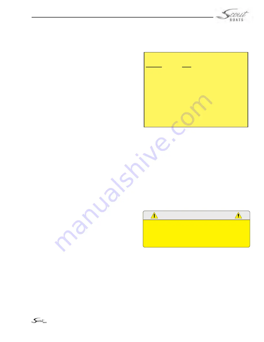
All wires in the electrical systems are color coded
to make identifying circuits easier. Wiring sche-
matics have been included with this manual to
aid in following an individual circuit of the boat.
6.2 12 Volt DC System & Batteries
The 12 volt system is a fairly standard marine
system. There are four batteries, one for the
starboard engine, one for the port engine and
two batteries wired in parallel for the house and
electronics.
The batteries for the engines, house and elec-
tronics are located in a compartment below the
helm and accessed through a hatch in rear cabin
bulkhead. They are controlled by three battery
switches, one for the port engine, one for the
starboard engine and one for the house 12 volt
accessories and electronics. The batteries them-
selves can be charged by the engines or by the
battery charger when connected to shore power.
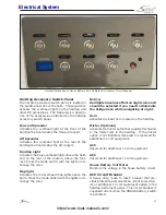
Most 12 volt power is distributed to the 12 volt
accessories through individual circuit breakers
located in the cabin DC panel or by fuses in the
CZone control modules. All circuit breakers and
fuses are labeled by the name of the circuit they
protect. Main circuit breakers in the cabin DC
panel protect the primary circuits for the CZone
control modules, windlass, continuous power and
electronics. Additional “push to reset” breakers
in the DC panel protect the circuits for the trim
tabs, stereo & electronics memory, CZone display,
NEMA controller, CO Alarm, 12V outlet and wind-
lass control switches. Most 12 volt accessories are
operated directly by switches in the helm switch
panel, hardtop switch panel or switches in the
cabin. Other accessories are controlled directly
with the CZone display.
Main breakers or fuses located on each engine
protect the ignition systems and gauges. Ya-
maha and Mercury engine electrical circuits are
protected by fuses located in a fuse panel on the
side of the engine. The fuse panel is equipped
with a spare fuse for each circuit. Always replace
fuses used with the fuse specified by the engine
manufacturer. Refer to the engine owner’s manual
for more information on the fuses, fuse panels or
circuit breakers on your engines.
CAUTION
PROPER FUSE OR BREAKER PROTECTION MUST BE PROVIDED
FOR ALL 12 VOLT EQUIPMENT ADDED. DO NOT OVERLOAD
THE ACCESSORY CIRCUIT BREAKERS OR OTHER CIRCUITRY
THROUGH ADDITIONAL 12 VOLT EQUIPMENT.
Batteries and Battery Switches
The DC electrical system on your boat is designed
for wet cell or absorbed glass mat (AGM) marine
batteries. Do not attempt to use gel cell or other
non wet cell batteries. The engine charging sys-
tem and the battery charger are not designed to
recharge these batteries which could cause unusu-
ally short battery life, engine starting problems
and damage to the DC charging systems. You
also should not mix the size or brand of marine
Chapter 6:
ELECTRICAL SYSTEM
Scout Boats Marine Standard Wiring Code
COLOR
USE
Brown (Br)
Pumps
Orange (O)
Accessory Feed + 12 VDC
Dark Blue
Cabin/Courtesy/Instrument Lighting
Pink (Pk)
Fuel Sender
Dark Gray (Gy)
Navigation Lighting
Black or Yellow
12 VDC Ground
Purple (Pu)
Ignition Instrument Feed + 12 VDC
Green (G)
DC Grounding (Bonding)
Red
+ 12 VDC Power
https://www.boat-manuals.com/
Summary of Contents for 300 LXF
Page 2: ...2 Rev 0 Print Date 11 7 2016 https www boat manuals com ...
Page 8: ...8 NOTES https www boat manuals com ...
Page 12: ...12 NOTES https www boat manuals com ...
Page 18: ...18 NOTES https www boat manuals com ...
Page 27: ...27 Operation https www boat manuals com ...
Page 40: ...40 NOTES https www boat manuals com ...
Page 60: ...60 NOTES https www boat manuals com ...
Page 86: ...86 NOTES https www boat manuals com ...
Page 98: ...98 NOTES https www boat manuals com ...
Page 122: ...122 NOTES https www boat manuals com ...
Page 130: ...130 NOTES https www boat manuals com ...
Page 155: ...155 MAINTENANCE LOG Appendix C Date Hours Dealer Service Repairs https www boat manuals com ...
Page 156: ...156 Maintenance Log Date Hours Dealer Service Repairs https www boat manuals com ...
Page 157: ...157 Maintenance Log Date Hours Dealer Service Repairs https www boat manuals com ...
Page 158: ...158 Maintenance Log Date Hours Dealer Service Repairs https www boat manuals com ...
Page 159: ...159 Maintenance Log Date Hours Dealer Service Repairs https www boat manuals com ...
Page 160: ...160 Maintenance Log Date Hours Dealer Service Repairs https www boat manuals com ...
Page 161: ...161 Appendix D https www boat manuals com ...
Page 162: ...162 Boating Accident Report https www boat manuals com ...
Page 163: ...163 Boating Accident Report https www boat manuals com ...
Page 164: ...164 NOTES https www boat manuals com ...
Page 166: ...166 NOTES https www boat manuals com ...
Page 172: ...172 https www boat manuals com ...
Page 173: ...173 Scout Boats Inc 2531 Hwy 78 West Summerville SC 29483 https www boat manuals com ...


