77
Electrical System
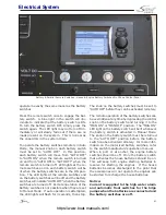
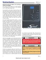
PWR
LEAKAGE
FAULT
TEST
ELCI/INLET
CIRCUIT BREAKER
ELCI/INLET Circuit Breaker Panel
WARNING
UNDETECTED FAULTS IN THE AC ELECTRICAL SYSTEM
COULD CAUSE THE WATER AROUND THE BOAT TO BECOME
ENERGIZED. THIS COULD CAUSE A SEVERE SHOCK OR EVEN
DEATH TO SOMEONE IN THE WATER NEAR THE BOAT. NEVER
SWIM OR ALLOW SWIMMING AROUND THE BOAT WHEN THE AC
SYSTEM IS ACTIVATED BY THE SHORE POWER CONNECTION
OR GENERATOR.
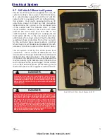
Disconnecting procedure for shore power
connection:
Turn the main breakers on the cabin AC panel and
shore power inlet panel to the OFF position. Turn
the disconnect breaker on the dockside outlet to
the OFF position.
Disconnect the cable from the dockside outlet and
replace the outlet caps. Disconnect the cable from
the boat and replace the outlet cap. Store cable.
Equipment Leakage Circuit Interrupter
The ELCI provides whole-boat ground fault protec-
tion (electrical shock protection from stray cur-
rent) for the entire AC shore power system. The
ELCI face plate on the inlet panel is equipped with
a TEST button. There are also two LED lights that
indicate circuit status. When the 120 volt AC sys-
tem is activated, the green “POWER” LED should
show steady illumination and the red “LEAKAGE
FAULT” LED should remain off.
The ELCI trips and opens the inlet main circuit
when there is a ground fault condition. If the
red “LEAKAGE FAULT” LED is continuously illumi
-
nated the ELCI has tripped the inlet breaker due
to a ground fault condition. Some faults are self
correcting. If it trips, try resetting the ELCI/inlet
breaker once. If the green LED shows steady il-
lumination and the ELCI does not trip again, the
circuit is OK. If the ELCI/inlet breaker continues
to trip and the red LED is lit after being reset there
is a problem with the AC electrical system and it
is unsafe to use. Make sure all main breakers are
turned off and notify a qualified marine electrician
to check the wiring and correct the problem.
It is important that the ELCI is working properly
to provide protection against electric shock. It
should be tested at least once each month to en-
sure proper operation by pressing the TEST button
in the faceplate. Refer the ELCI instructions for
the testing procedure.
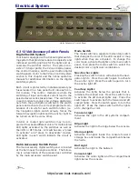
120 Volt Cabin Circuit Breaker Panel
The AC/DC breaker panel is located in the cabin
near the cabin door. The 120 volt AC circuit break-
ers are located at top of the panel.
The following is a description of the AC panel
equipment and circuit breakers that protect
the accessories:
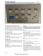
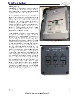
AC Volt Meter
The meter located in the cabin breaker panel
monitors the voltage when the boat is connected
to AC power. The voltage should be checked each
time the AC system is activated. The AC system
and accessories can be damaged by voltage that
is below 105 volts or above 125 volts. You should
monitor the voltage and never operate your AC
electrical system if the voltage is below or above
this range.
Line voltage, frequency and current draw can
also be monitored using the CZone display panel.
To monitor the AC power supply with the CZone
display panel, select to monitor the AC power sup-
https://www.boat-manuals.com/
Summary of Contents for 300 LXF
Page 2: ...2 Rev 0 Print Date 11 7 2016 https www boat manuals com ...
Page 8: ...8 NOTES https www boat manuals com ...
Page 12: ...12 NOTES https www boat manuals com ...
Page 18: ...18 NOTES https www boat manuals com ...
Page 27: ...27 Operation https www boat manuals com ...
Page 40: ...40 NOTES https www boat manuals com ...
Page 60: ...60 NOTES https www boat manuals com ...
Page 86: ...86 NOTES https www boat manuals com ...
Page 98: ...98 NOTES https www boat manuals com ...
Page 122: ...122 NOTES https www boat manuals com ...
Page 130: ...130 NOTES https www boat manuals com ...
Page 155: ...155 MAINTENANCE LOG Appendix C Date Hours Dealer Service Repairs https www boat manuals com ...
Page 156: ...156 Maintenance Log Date Hours Dealer Service Repairs https www boat manuals com ...
Page 157: ...157 Maintenance Log Date Hours Dealer Service Repairs https www boat manuals com ...
Page 158: ...158 Maintenance Log Date Hours Dealer Service Repairs https www boat manuals com ...
Page 159: ...159 Maintenance Log Date Hours Dealer Service Repairs https www boat manuals com ...
Page 160: ...160 Maintenance Log Date Hours Dealer Service Repairs https www boat manuals com ...
Page 161: ...161 Appendix D https www boat manuals com ...
Page 162: ...162 Boating Accident Report https www boat manuals com ...
Page 163: ...163 Boating Accident Report https www boat manuals com ...
Page 164: ...164 NOTES https www boat manuals com ...
Page 166: ...166 NOTES https www boat manuals com ...
Page 172: ...172 https www boat manuals com ...
Page 173: ...173 Scout Boats Inc 2531 Hwy 78 West Summerville SC 29483 https www boat manuals com ...

