background image

Boly Media

SG550 series 

Appendix 

:Technical Specifications 

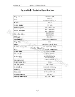
Appendix

: Technical Specifications 


Image Sensor   

5MP Color CMOS   

Lens 

F=3.1mm   

FOV(Field of View)=40°     

IR-Flash  

10-12m 

Control Display   

1.7" LCD   

Ext. Memory Card 

From 8 MB to 8 GB 

Picture  Resolution 

5MP = 2560x1920   

3MP = 2048x1536 

Video  Resolution 

640x480(16fps)  

320x240(20fps)  

PIR Sensor 

Multi Zone   

PIR Sensitivity 

Adjustable(High/Normal/Low)  

Trigger Time   

1.2s 

Weight  

About 0.22 kg without battery   

Operation/Storage Tem. 

-20 - +60°C / -30 - +70°C 

Delay  

1s 

  60 min. Programmable   

Capture Mode 

1

3 Programmable   

Video Length   

1

60s Programmable   

Power Supply   

8xAA(Recommended)  

4xAA(Emergency)  

Stand-by Current 

< 0.25mA(<6mAh/Day)   

Power Consumption 

150mA 

Low Battery Alert 

LED Indicator   

User Interface 

Control with LCD display   

Mounting  

Rope/Belt/Python lock 

Dimensions 

  13* 8*5 cm/5*3*2 inches 

Operation Humidity 

5% - 90% 

Security authentication 

FCC,  CE,  RoHS 

Page 28 

Boly Media Communications

Summary of Contents for SG550 Series

Page 1: ...Boly Media Infrared Digital Scouting Camera User s Manual for SG550 Series For Model SG550 SG550V SG550B SG550VB Boly Media Communications ...
Page 2: ...1 2 Formatting the SD Card 11 4 1 3 Setting Pixel Size 12 4 1 4 Setting Video Size 13 4 1 5 Setting Date and Time 13 4 1 6 Setting Continuous Shooting Numbers 16 4 1 7 Setting Video Length 17 4 1 8 Setting Triggering Interval Time 18 4 1 9 Setting PIR Sensitivity 19 4 1 10 Setting Time Stamp 19 4 1 11 Setting Timer 20 4 1 12 Resetting to Default Settings 22 4 2 Playing back and Deleting Operations...

Page 3: ...ctures or videos manually by pressing the capture button on the wired control 1 2 Application The camera can be used as automatic surveillance device for guarding and recording unexpected intrusion to homes shops schools depots offices taxies worksites etc It can also be used as trail camera for hunting or monitoring animals by recording the traces of wild animals It can be left alone for weeks an...

Page 4: ...Boly Media SG550 series 1 Instruction Figure 1 Front view of the camera Figure 2 Buttons of the control and icons on the screen Page 2 Boly Media Communications ...
Page 5: ... opening the bottom cover please make sure that the write protect of the card is disabled so that it is writable The supported card size of the device is between 8MB and 8GB For SG550 SG550V model the file format supported is FAT12 and FAT16 while for SG550B SG550VB model the camera supports only one kind of file system format FAT32 It is recommended to use the SD card with a quality guarantee Pag...

Page 6: ...he SD card when the power switch is at ON position Please set the TV in the AV IN mode when connecting a TV The camera will be in USB mode when connected to a USB port of a computer In this case the SD card functions as a removable disk no matter the power switch of the device is ON or OFF Turning the power ON will force the camera into test mode when the control is connected to the camera otherwi...

Page 7: ...eight new high performance alkaline AA batteries Internally the batteries are divided into two paralleled groups each group contains four batteries and can supply power for the camera alone with shorter battery life time The device has four battery slots as shown in Fig 4 a The bottom cover of the battery cabinet is shown in Fig 4 b Slot 1 and 2 form one group while slot 3 and 4 form the other gro...

Page 8: ...pability greater than 1000mA However under sufficient daylight at day time the camera can work with much less current 400mA Please use the power source cable included to connect the external DC power source and insert it into the power jack of the camera be sure that the polarity is correct If both external power source and batteries are connected the camera will be powered by the external power s...

Page 9: ...ock it to fix the camera on a tree and to walk away After entering into the LIVE mode no manual controls are needed and possible The camera will take pictures or videos automatically according to the previous programmed settings when human or animals enter into the monitoring region If the device is previously in the TEST mode you just need disconnect the control from the camera in order to let th...

Page 10: ...deo has its own file name Before entering into the LIVE mode please pay attention to the following a The polarities of the power are correct and the power is sufficient b The SD card has sufficient space and its write protection is disabled c Power switch at ON position d Control is disconnected e Avoiding temperature and motion disturbances in front of the device such as big leaf curtain air cond...

Page 11: ...n run a commercial program with an image browser e g ACDSee or an image browser built in the operating system to view images which saved in the SD card 3 9 Powering Off Just put the power switch at the OFF position when you don t need to use it Please note that even in the OFF mode the camera still consumes certain power at μA level Therefore be sure to take the battery out of the battery slot if ...

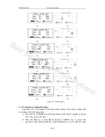
Page 12: ...nient Otherwise you may set parameters with the guide information shown on the LCD step by step For your convenience two methods of parameter settings are introduced In the first case we number the setting processes with small letters for LCD display while digits are used for the second case for TV display 4 1 1 Setting the Camera Mode Two ways are available for setting this parameter One is to us...

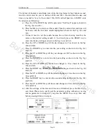
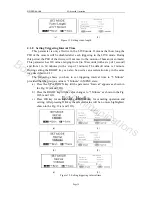
Page 13: ...SD card or not shown in the Fig 6 b and 6 2 c If you want to proceed the formatting process pressing the RIGHT key to change the value to Yes Yes will be highlighted shown in the Fig 6 c and 6 3 d Press the OK key to start formatting the SD card During formatting the guide information will be changed shown in the Fig 6 d and 6 4 Please note you ll quit the parameter setting without any saving and ...

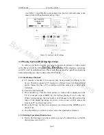
Page 14: ...ded that the previous value is 5M Pixel at MENU state a Press the UP or DOWN key till the parameter Image Size appears shown in the Fig 7 a and 7 1 b Press the RIGHT key the value will be changed to 3M Pixel shown in the Fig 7 b and 7 2 The value 3M Pixel is highlighted c Press OK key to save the current setting or MENU key for canceling the setting and quitting After pressing OK key the selected ...

Page 15: ...anged to 320x240 shown in the Fig 8 b and 8 2 c Press OK key to save the current setting or MENU key for canceling setting and exiting After pressing OK key the selected value will be no more highlighted shown in the Fig 8 c and 8 3 a 1 b 2 c 3 Figure 8 Setting video size 4 1 5 Setting Date and Time You can change the date and time of the device by setting this parameter when necessary e g after e...

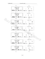
Page 16: ... as shown in the Fig 9 d and 9 4 e Press the RIGHT key to enter into the year setting as shown in the Fig 9 e and 9 5 f Press the UP or DOWN key till the year changes to 2007 as shown in the Fig 9 f and 9 6 g Press the RIGHT key to enter into the hour setting as shown in the Fig 9 g and 9 7 h Press the UP or DOWN key till the hour changes to 10 as shown in the Fig 9 h and 9 8 i Press the RIGHT key...

Page 17: ...Boly Media SG550 series 4 Advanced Operation b 2 c 3 d 4 e 5 f 6 g 7 h 8 i 9 Page 15 Boly Media Communications ...
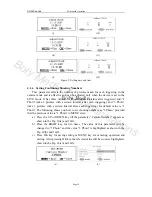
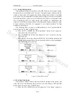
Page 18: ... certain interval after each triggering Its default value is 1 Photo The following shows you how to set shooting numbers as 3 Photo provided that the previous value is 1 Photo in MENU state a Press the UP or DOWN key till the parameter Capture Number appears as shown in the Fig 10 a and 10 1 b Press the RIGHT key for two times The value of this parameter will be changed to 3 Photo and the value 3 ...

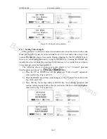
Page 19: ...seconds the step length will increase to 5 seconds first and then to 10 seconds per step a few seconds later The following shows you how to set video length to Avi 5 Second provided that the previous value is Avi 10 Second in MENU state a Press the UP or DOWN key till the parameter Video Length appears as shown in the Fig 11 a and 11 1 b Press the RIGHT key till the value changes to Avi 5 Second a...

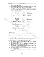
Page 20: ...ue is 1 minute During setting the RIGHT key can also be used as an acceleration key in the same way described in 4 1 7 The following shows you how to set triggering interval time to 5 Minute provided that the previous value is 1 Minute in MENU state a Press the UP or DOWN key till the parameter Interval appears as shown in the Fig 12 a and 12 1 b Press the RIGHT key till the value changes to 5 Min...

Page 21: ...r sensitivity for high temperature environment The following shows you how to set PIR sensitivity as Low provided that the previous value is Normal in MENU state a Press the UP or DOWN key till the parameter Sensor Level appears as shown in the Fig 13 a and 13 1 b Press the RIGHT key till the value changes to Low as shown in the Fig 13 b and 13 2 c Press OK key for saving setting or MENU key for c...

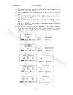
Page 22: ...minute ranges from 0 to 59 The setting of this parameter is similar to that of date and time Please note that the start and stop time can only be effective when the timer is set to the value of On Provided that the device should work from eight clock a m to five clock p m in MENU state detailed operations are as following a Press the UP or DOWN key till the parameter Timer Switch appears as shown ...

Page 23: ...own in the Fig 15 h and 15 8 i Press the RIGHT key to set minute of stop time as shown in the Fig 15 i and 15 9 j Press the UP or DOWN key till the minute of stop time changes to 0 as shown in the Fig 15 j and 15 10 k Press OK key for saving timer setting or MENU key for canceling operation and exiting After pressing OK key the selected value will be no more highlighted shown in the Fig 15 k and 1...

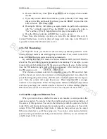
Page 24: ... load the default settings This can be simply done according to the following steps a Press the UP or DOWN key till the parameter Default Set appears as shown in the Fig 16 a and 16 1 b Press the OK key to load default settings or MENU key to cancel this operation After pressing OK key related parameters are set to default values Page 22 Boly Media Communications ...
Page 25: ...e Therefore connect a TV monitor or a Picture Viewer such as a digital picture frame that has a TV in interface with the camera by a video cable included b Enter into the Test mode c Press the OK key Then the latest picture or video will be displayed on the TV It is needed to press SHOT key for starting playing if it is a video clip When viewing images the total number of all images in the SD card...

Page 26: ...fix the camera and then walk away In this waiting time the PIR indication light red will blink continuously After the light is put off the PIR starts to work When human or animals enter into the monitoring range the PIR can detect them and then the camera starts to take picture s or video as programmed According to the pre defined triggering interval time the PIR can be reactivated after the time ...

Page 27: ...med folder Each new image or video will be numbered incrementally by shooting time The saving name likes IM000001 JPG or IMAG0001 JPG or IM000001 AVI or IMAG0001 AVI Through the suffix you can distinguish whether the file is an image with suffix jpg or a video with suffix avi 4 7 Installing Driver for the SD Card If your computer can not recognize the USB port of the camera e g your system is Wind...

Page 28: ...ase bring the device to an appointed maintenance for repairing WARNING Upgrade is risky please be cautious 4 9 Factory Default When leaving the factory most commonly used parameters usually have their default for the product These values are all optimal or commonly used The predetermined values of primary parameters for the camera are shown in table 1 in 3 7 Page 26 Boly Media Communications ...

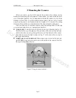
Page 29: ...re three ways to mount the camera using a band shaped belt a round rope or a round steel cable lock or a combination of the above z Using the belt To use the belt to fix the camera on a tree is illustrated in Fig 17 Take the belt toe to go through one of the ear holes of the camera from the back and then the other one also go through the other ear from the back of the camera Next take two toes to ...

Page 30: ...nsitivity Adjustable High Normal Low Trigger Time 1 2s Weight About 0 22 kg without battery Operation Storage Tem 20 60 C 30 70 C Delay 1s 60 min Programmable Capture Mode 1 3 Programmable Video Length 1 60s Programmable Power Supply 8xAA Recommended 4xAA Emergency Stand by Current 0 25mA 6mAh Day Power Consumption 150mA Low Battery Alert LED Indicator User Interface Control with LCD display Mount...

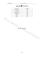
Page 31: ... SG550 series Appendix Ⅱ Part List AppendixⅡ Parts List Part Name Quantity Digital camera One Control One External DC cable One TV out cable One USB cable One Belt One Manual One Page 29 Boly Media Communications ...

Reviews: