SG968K-10M
1 Instruction
Page
2
automatically in digital format.
1.3
Camera Overview
1.3.1
Diagram of camera functional indicators
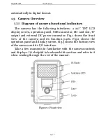
The camera has the following interfaces: a 2.0’’ TFT LCD
display screen, operation panel, USB connector, SD card slot, TV
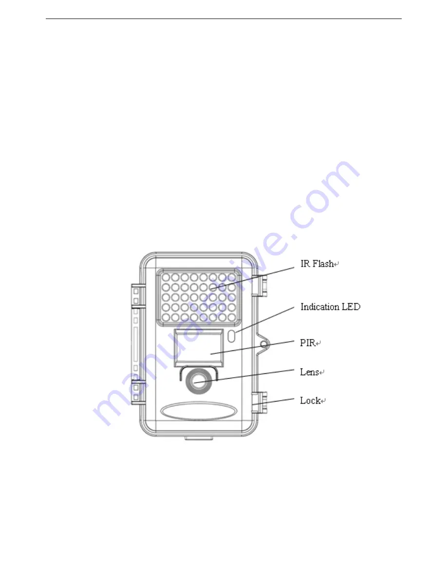
output and external DC power connector. Fig.1 shows the front
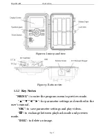
view of the camera and its function parts. Fig.2 shows the
operation panel and display screen. Fig.3 shows the bottom view
of the camera and its I/O interface.
Take a few moments to familiarize with the camera controls
and displays. It is helpful to bookmark this section and refer to it
when reading through the rest of the manual.
Figure 1: Front view


