36
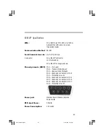
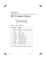
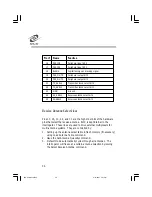
Pin # Name
Function
16
PER_IN3
Peripheral input bit 3
17
PER_IN1
Peripheral input bit 1
18
BLANK
Digital test signal: blanking signal
19
PER_OUT5
Peripheral output bit 5
20
PER_OUT3
Peripheral output bit 3
21
TX_ASEL4
Transmit antenna select bit 4
22
TX_ASEL2
Transmit antenna select bit 2
23
GND
Ground
24
RX_ASEL4
Receive antenna select bit 4
25
RX-ASEL2
Receive antenna select bit 2
Receive Antenna Select Lines
Pins 13, 25, 12, 24, and 11 are the high order bits of the hardware
pins that select the receive antenna. Bit 0 is kept internal to the
interrogator. These lines are used to drive external multiplexers for
multi-antenna systems. They are controlled by:
1. Setting up the antenna select table in flash memory (if necessary)
using Load Antenna Table command.
2. Issue the Set Antenna Quantity command.
3. Default mode automatically cycles through all antennas. The
interrogator will freeze at a certain antenna selection by issuing
the Select Receive Antenna command.
556-EP Manual.P65
2/27/2001, 3:21 PM
36

