background image

1.

About Your System  . . . . . . . . . . . . . . . . . . . . . . . . . . . . . . . . . . . . . . . . . . . . . . . . . . . .Page 1

2.

Remote Transmitters  . . . . . . . . . . . . . . . . . . . . . . . . . . . . . . . . . . . . . . . . . . . . . . . . . . .Page 2

Remote Transmitter Description . . . . . . . . . . . . . . . . . . . . . . . . . . . . . . . . . . . . . . .Page 2
Adding/Replacing Transmitters  . . . . . . . . . . . . . . . . . . . . . . . . . . . . . . . . . . . . . . .Page 3
Two Car Operation  . . . . . . . . . . . . . . . . . . . . . . . . . . . . . . . . . . . . . . . . . . . . . . . .Page 3
Battery Replacement  . . . . . . . . . . . . . . . . . . . . . . . . . . . . . . . . . . . . . . . . . . . . . .Page 3

3.

System Operation  . . . . . . . . . . . . . . . . . . . . . . . . . . . . . . . . . . . . . . . . . . . . . . . . . . . . .Page 6

Remote Locking  . . . . . . . . . . . . . . . . . . . . . . . . . . . . . . . . . . . . . . . . . . . . . . . . . .Page 6
Remote Unlocking  . . . . . . . . . . . . . . . . . . . . . . . . . . . . . . . . . . . . . . . . . . . . . . . .Page 6
Optional Panic Mode . . . . . . . . . . . . . . . . . . . . . . . . . . . . . . . . . . . . . . . . . . . . . . .Page 6 
Valet Mode  . . . . . . . . . . . . . . . . . . . . . . . . . . . . . . . . . . . . . . . . . . . . . . . . . . . . .Page 6

4.

Remote Start Features  . . . . . . . . . . . . . . . . . . . . . . . . . . . . . . . . . . . . . . . . . . . . . . . . .Page 7

Remote Starting . . . . . . . . . . . . . . . . . . . . . . . . . . . . . . . . . . . . . . . . . . . . . . . . . .Page 7
Shut Down  . . . . . . . . . . . . . . . . . . . . . . . . . . . . . . . . . . . . . . . . . . . . . . . . . . . . .Page 7
Quick Stop  . . . . . . . . . . . . . . . . . . . . . . . . . . . . . . . . . . . . . . . . . . . . . . . . . . . . .Page 7
Automatic Start Mode . . . . . . . . . . . . . . . . . . . . . . . . . . . . . . . . . . . . . . . . . . . . . .Page 8 
Starter Diagnostics  . . . . . . . . . . . . . . . . . . . . . . . . . . . . . . . . . . . . . . . . . . . . . . . .Page 8 

5.

Extended Features  . . . . . . . . . . . . . . . . . . . . . . . . . . . . . . . . . . . . . . . . . . . . . . . . . . . .Page 9

Ignition Door Locking  . . . . . . . . . . . . . . . . . . . . . . . . . . . . . . . . . . . . . . . . . . . . . .Page 9
Ignition Door Unlocking  . . . . . . . . . . . . . . . . . . . . . . . . . . . . . . . . . . . . . . . . . . . .Page 9
Dome Light Activation  . . . . . . . . . . . . . . . . . . . . . . . . . . . . . . . . . . . . . . . . . . . . .Page 9
Auxiliary Function Outputs  . . . . . . . . . . . . . . . . . . . . . . . . . . . . . . . . . . . . . . . . . .Page 9
Turbo Timer Feature . . . . . . . . . . . . . . . . . . . . . . . . . . . . . . . . . . . . . . . . . . . . . . .Page 9

6.

System Installation  . . . . . . . . . . . . . . . . . . . . . . . . . . . . . . . . . . . . . . . . . . . . . . . . . . .Page 10

Mounting the Control unit  . . . . . . . . . . . . . . . . . . . . . . . . . . . . . . . . . . . . . . . . . .Page 10

7.

System Wiring   . . . . . . . . . . . . . . . . . . . . . . . . . . . . . . . . . . . . . . . . . . . . . . . . . . . . . .Page 11

6-Pin Starter Harness  . . . . . . . . . . . . . . . . . . . . . . . . . . . . . . . . . . . . . . . . . . . . .Page 11
20-Pin Main Harness . . . . . . . . . . . . . . . . . . . . . . . . . . . . . . . . . . . . . . . . . . . . . .Page 11
Plug-in Connectors  . . . . . . . . . . . . . . . . . . . . . . . . . . . . . . . . . . . . . . . . . . . . . . .Page 12

8.

Jumper Settings  . . . . . . . . . . . . . . . . . . . . . . . . . . . . . . . . . . . . . . . . . . . . . . . . . . . . .Page 13

Jumper Selection  . . . . . . . . . . . . . . . . . . . . . . . . . . . . . . . . . . . . . . . . . . . . . . . .Page 13

9.

System Programming  . . . . . . . . . . . . . . . . . . . . . . . . . . . . . . . . . . . . . . . . . . . . . . . . .Page 14

Entering System Programming . . . . . . . . . . . . . . . . . . . . . . . . . . . . . . . . . . . . . . .Page 14
Default Reset  . . . . . . . . . . . . . . . . . . . . . . . . . . . . . . . . . . . . . . . . . . . . . . . . . . .Page 14
Programmable System Options  . . . . . . . . . . . . . . . . . . . . . . . . . . . . . . . . . . . . . .Page 14
Branch Table  . . . . . . . . . . . . . . . . . . . . . . . . . . . . . . . . . . . . . . . . . . . . . . . . . . .Page 15

10.   Wiring Diagrams  . . . . . . . . . . . . . . . . . . . . . . . . . . . . . . . . . . . . . . . . . . . . . . . . . . . . .Page 17 
11.   Door Lock Diagrams  . . . . . . . . . . . . . . . . . . . . . . . . . . . . . . . . . . . . . . . . . . . . . . . . . .Page 18 
12.

Two Stage Door Lock Diagrams  . . . . . . . . . . . . . . . . . . . . . . . . . . . . . . . . . . . . . . . . . .Page 19

13.

Technical Information  . . . . . . . . . . . . . . . . . . . . . . . . . . . . . . . . . . . . . . . . . . . . . . . . .Page 23

14.  Wiring Diagram  . . . . . . . . . . . . . . . . . . . . . . . . . . . . . . . . . . . . . . . . . . . . . . . . . . . .Back Page

T

Ta

ab

blle

e o

off C

Co

on

ntte

en

ntts

s

Summary of Contents for Galaxy 2000RS Plus SERIES

Page 1: ...2 20 00 00 0R RS S P PL LU US S S SE ER RI IE ES S REMOTE START SYSTEM PRODUCT MANUAL ...

Page 2: ...t 12 month warranty period there will be a maximum service charge of 25 00 per calendar year if required for repair and or replacement of any defective parts A copy of the original purchase receipt must accompany any products returned for warranty service Warranty is limited to defective parts and or replacement parts only and excludes any incidental and consequential damages connected therewith T...

Page 3: ...e 9 Ignition Door Unlocking Page 9 Dome Light Activation Page 9 Auxiliary Function Outputs Page 9 Turbo Timer Feature Page 9 6 System Installation Page 10 Mounting the Control unit Page 10 7 System Wiring Page 11 6 Pin Starter Harness Page 11 20 Pin Main Harness Page 11 Plug in Connectors Page 12 8 Jumper Settings Page 13 Jumper Selection Page 13 9 System Programming Page 14 Entering System Progra...

Page 4: ......

Page 5: ...t the vehicle is to be serviced System Contents Main Unit with built in ScyNet Network Interface Port Two 5 Button Random Code Remote Transmitters Status LED Coded Emergency Override Valet Switch Optional ScyNet Network Interface Accessories ScyNet Network Interface Software Two Way FM Paging Module w LCD Transmitter Options and Convenience Features This ScyTek system includes several optional inp...

Page 6: ...the next page allowing access to another set of features Once shifted to another page there are 4 pages total the transmitter will remain on that page for 10 seconds or until a button is pressed then return to page 1 Each time a transmitter button is pressed and held the LED will flash a number of times to indicate from which page it is transmitting Under normally operation only pages 1 and 2 are ...

Page 7: ...tters are to be used with both cars program transmitters A and B into the first vehicle in the manner described above Program transmitters C and D by pressing the Shift button twice before performing steps 3 and 4 above When finished programming the first vehicle program transmitters C and D into the second vehicle as normal then program transmitters A and B by pressing the Shift button twice befo...

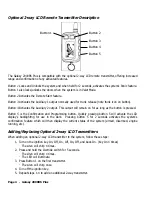
Page 8: ...ssed Button 5 is the Confirmation and Programming button Quickly pressing button 5 will activate the LCD display s backlighting for use in the dark Pressing button 5 for 2 seconds activates the system s confirmation feature which will then display the current status of the system armed disarmed engine running etc Adding Replacing Optional 2 way LCD Transmitters When adding an optional 2 way LCD tr...

Page 9: ...he system s operating range will decrease the LCD display will show only one of three bars in the battery icon or the display and sounds may suddenly stop and start as the battery voltage drops below minimum In order to change the battery first slide the battery door locking pin to the side Carefully slide the battery cover downward until it is free While replacing the battery make sure that the p...

Page 10: ...utton 1 for 3 seconds The horn will honk if connected The parking lights will flash The doors will unlock allowing access to the vehicle 2 Press Button 2 to stop Panic Mode If the ignition is on when the Panic feature is activated the doors will lock for personal safety If not deactivated using Button 2 the Panic Mode will automatically exit after 30 seconds and the system will be restored to its ...

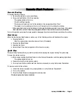
Page 11: ...ure is active any of the following actions will shutdown the engine 1 Pressing Button 4 After the engine shuts down the doors will lock if installed 2 Pressing the Brake Pedal 3 Opening the Hood 4 Remote Start Time Out completion of the timed run cycle Quick Stop The Quick Stop Feature allows you exit the vehicle while keeping the engine running for quick stops To leave the vehicle running 1 While...

Page 12: ...Ignition in Off position 3 Press the Valet switch within three seconds Side lights will flash indicating that the Cold Start mode has been activated To turn off Auto Cold Starting do one of the following Turn on the ignition Lock and Unlock using the remote Panic the system S St ta ar rt te er r D Di ia ag gn no os st ti ic cs s Starter doesn t start and Side Lights flash 3 Times Engine RPM not de...

Page 13: ...f control auxiliary lighting audio video system control and more The Pulsed operation setting allows an output to activate as long as the button is held The Timed operation setting allows an output to activate when the transmitter button is pressed and remain activated for 10 seconds or until the transmitter button is pressed again Note With the optional ScyNet network interface and Wizard softwar...

Page 14: ...or testing vehicle circuits Never use a test light 10 Always look before drilling any holes or mounting self tapping screws Be sure fuel lines and exterior wiring looms are clear as they are often close to the chassis and difficult to see 11 Protect all wires running from the engine compartment to the interior of the vehicle by covering with electrical tape and split loom tubing Be sure to use a g...

Page 15: ...optional feature such as power window activation etc This output may be programmed for momentary timed or latched operation Pin 4 BLACK WHITE WIRE Dome Light Output 500 mA Connect to the wire that activates the vehicle s dome light usually the door pin switch wire NOTE The dome light output can usually connect to the same wire used for the door trigger input see Green and Violet door trigger wires...

Page 16: ...e WHITE wire to the vehicle s headlight circuit Pin 20 BROWN WHITE WIRE Horn Output 500 mA Connect to a relay to honk the vehicle s horn when the panic feature is triggered This wire may instead be programmed as an ignition 3 relay trigger Plug in Connectors 4 Pin White Connector Auxiliary start input port for use with after market security system WHITE WIRE 3 pulse remote start Parking Brake inpu...

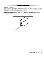
Page 17: ...er will be visible next to the parking light relay Set the jumper for the correct polarity output as described below then reassembly the main unit case Parking Light Output Selects the polarity for the output of the on board Parking Light relay Left Pin Center Pin positive Right Pin Center Pin negative J Ju um mp pe er r S Se et tt ti in ng gs s default setting shown ...

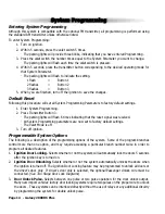
Page 18: ...signal was received All System Programming parameters are now set to factory default settings The Valet Mode is off 3 Turn off ignition Programmable System Options The following is a description of the programming options of the system Some of the program branches control more than one option and may require accessing a particular branch number twice in order to program all desired features 1 Igni...

Page 19: ...ected activating the Auxiliary 1 output usually used to open the trunk will disarm the alarm 9 Start in Valet Mode Selects whether or not the vehicle can remote start while in the valet mode 10 Lock After Start When selected the doors will automatically lock after remote starting 11 Lock After Shutdown When selected the doors will automatically lock after remote shutdown 12 Engine Run Time Selects...

Page 20: ... the tach signal was not learned Gas Engine Sets the engine type for Gasoline Diesel Engine Sets the engine type for Diesel and monitors the glow plug input to make sure the glow plugs are warm before cranking the starter If the glow plug wire is not connected the built in timer waits 15 seconds before automatically cranking the starter 16 FM Transmitter Program Programs the optional FM module and...

Page 21: ...tive Dome Negative Dome TO POSITIVE HORN WIRE 12V Brown White HORN OUTPUT TO NEGATIVE HORN WIRE 12V Brown White HORN OUTPUT Positive Horn Negative Horn Blue Yellow Wire GLOW PLUG INPUT Yellow Wire IGNITION GLOW PLUG WIRE FROM VEHICLE 12V Yellow Wire IGNITION Violet Wire STARTER TO STARTER IGNITION SWITCH Orange wire ANTIGRIND A C C L O CK ON S T A R T Negative Glow Plug Starter Anti Grind ...

Page 22: ...gger Reverse Polarity Vacuum Adding Actuator Follow the diagrams below for connecting basic door lock systems For Two Stage door lock systems separately unlocks driver and passenger doors see following pages D Do oo or r L Lo oc ck k D Di ia ag gr ra am ms s ...

Page 23: ...Two Stage Negative Trigger Two Stage Positive Trigger The Galaxy Starter is equipped with a dedicated Passenger Unlock output allowing Two Stage Door Lock operation When connected as shown below unlocking the system will unlock only the driver s door Pressing the unlock button again will unlock all doors ...

Page 24: ...Page 20 Galaxy 2000RS Plus T Tw wo o S St ta ag ge e D Do oo or r L Lo oc ck k D Di ia ag gr ra am ms s c co on nt t d d Two Stage Reverse Polarity Two Stage Adding Actuator ...

Page 25: ...Galaxy 2000RS Plus Page 21 ...

Page 26: ...Page 22 Galaxy 2000RS Plus ...

Page 27: ... FCC Rules Operation is subject to the following two conditions 1 This device may not cause harmful interference 2 This device must accept any interference received including interference that may cause undesired operation T Te ec ch hn ni ic ca al l I In nf fo or rm ma at ti io on n ...

Page 28: ...ScyTek Electronics 11627 Cantara Street Unit B North Hollywood CA 91605 ScyTek Electronics 2003 Galaxy Starter r5 2 18 04 W Wi ir ri in ng g D Di ia ag gr ra am m ...

Reviews: