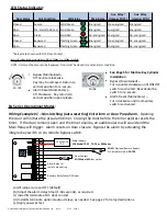
Wiring Example #2 – Latching (Manually Reset) Exit Alarm/Door Prop Alarm
.
Opening the door
will initiate the pre-alarm timer. Closing the door before the timer expires resets the timer. If the
door remains open and the timer expires, an audible alarm will sound and the Main Relay will
trigger & latch. Alarm must be reset by using the integral key switch (EA-708 or EA-728 only), or by
remote control switch. Bypass the alarm by activating the integral key switch or via remote switch.
(a) Jumpers 1 & 5 are installed. Jumpers 2, 3, & 4 are set OFF.
(b) Adjust the alarm delay timer (1-60 seconds), as required.
(c) Install Remote reset switch. Required for EA-SN; Optional for EA-708 or EA-728.
(d) Install & terminate a N/C door contact.
(e) Install & terminate optional output relays, as needed. See page 2 for relay descriptions.
(f) Apply power & test.
12 or 24VDC
P.S.
N/C
N/O
Door Contact:
SDC Model MC-4
or similar
Alarm Relay for
remote monitoring
Power Supply:
SDC Model TR-12, TR-24, or 600 Series
Auxiliary Relay changes state when the unit
enters bypass mode or alarm mode
P:\INSTALLATION INST\Accessories\INST-DOOR PROP.vsd Rev A 07-17 Page 4
PWR (-)
PWR (+)
NO
NO
NC
NC
C
C
1
2
3
4
5
1s
60s
EA-SN
: Requires Remote Reset Switch;
Pre-wired for model
EA-728
Wiring Example #3 – Double-Door Latching Exit Alarm/Door Prop Alarm with Timed Reset
.
Opening the door will initiate the pre-alarm timer. Closing the door before the timer expires resets
the timer. If the door remains open and the timer expires, an audible alarm will sound and the
Main Relay will trigger & latch. The alarm will automatically reset 60 seconds after door closure.
The alarm may also be reset by using the integral key switch (EA-708 or EA-728 only), or by remote
control switch. Bypass the alarm by activating the integral key switch or via remote bypass switch.
12 or 24VDC
P.S.
N/C
N/O
Door Contacts:
SDC Model MC-4
(x2)
Alarm Relay for
remote monitoring
Power Supply:
SDC Model TR-12, TR-24, or 600 Series
EA-SN
: Requires Remote Reset Switch;
Pre-wired for the
EA-728
(a) Jumpers 1, 2 & 5 are installed. Jumpers 3 & 4 are set OFF.
(b) Adjust the alarm delay timer (1-60 seconds), as required.
(c) Install Remote reset switch. Required for EA-SN; Optional for EA-708 or EA-728.
(d) Install & terminate N/C door contacts in series.
(e) Install & terminate optional output relays, as needed. See page 2 for relay descriptions.
(f) Apply power & test.
N/C
PWR (-)
PWR (+)
NO
NO
NC
NC
C
C
1
2
3
4
5
1s
60s
Auxiliary Relay changes state when the unit
enters bypass mode or alarm mode


