P:\INST-INS TRUCTIONS\CO NTROL CONSOLES \INST-TCC/RCC REV - 10/20 Page 12
3.0 CONSOLE WIRING EXAMPLES
Wiring examples are meant to serve as a reference and may not cover the scope of your exact application.
3.1
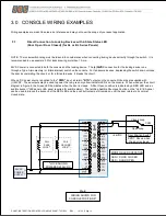
Direct Connection to Locking Devices with 2-State Status LED
(Door Open / Door Closed) (for AL or BL Series Panels)
NOTE: The rocker switch rating must be taken into consideration when connecting locking devices directly through the switch. It is
recommended to use example 3.3 for locks drawing more than 1 Amp.
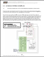
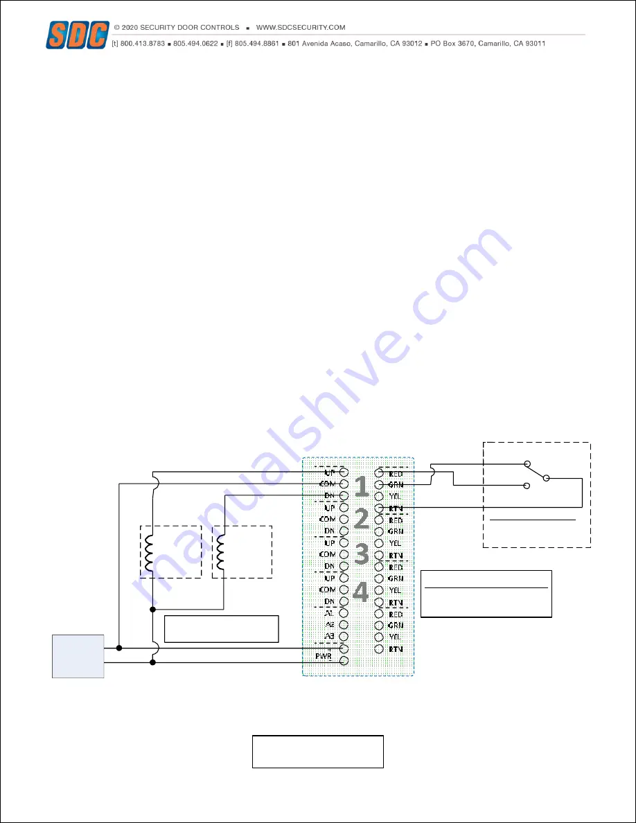
24VDC power is connected to both the console and the locking device. The
(+)24VDC
connection for the locking device runs
through a Type A (momentary) or B (maintained) switch on the console. For fail-secure devices, depressing the switch down unlocks
the door by completing the circuit, or for a fail-safe device, it breaks the circuit.
When a DC power source is applied to the
“PWR”
input, all return
“RTN”
outputs on the console I/O boards are supplied with
(+)24VDC. These outputs may be used to power the red, green or yellow indicator LED
’s on the console. When wired per the circuit
diagram in Figure 6, the Green LED illuminates when the door is closed. A Door Open condition is indicated by a RED LED and an
audible buzzer (*L4E panel or EA panel required for audible alarm). The latching Audible Shunt push button on the *L4E / EA panel
can be used to silence the buzzer, but the RED LED and the push button lamp will remain on until the door returns to its norm al
closed state.
+
-
-
+
FAIL
SAFE
LOCK**
FAIL
SECURE
LOCK**
24VDC
POWER
SUPPLY
(-)
(+)
**LOCK SHOWN
POWERED @ 24VDC
Closed Loop
COM
Open Loop
+24VDC
Door Position Switch
SPDT. Shown when
the door is closed.
MONITOR LED OPERATION
GRN = DOOR CLOSED
RED = DOOR OPEN
Fig 6.
WIRING SHOWN FOR
CONSOLE POSITION #1

