background image


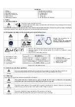
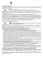
1.3.11 Filling with fuel


The fuel is highly flammable and its vapours are combustible. 
Filling should be carried out with the engine turned off. Smoking, using a naked flame or 
producing sparks are forbidden while the fuel tank is being filled. 
All traces of fuel should be wiped off with a clean cloth. 

Danger 

Storage and handling of petroleum products must be carried out in accordance with the law. Close the fuel tap (if fitted) each time the 
tank has been filled. Never top up fuel when the generating set is in operation or hot. 
Always place the generating set on a flat, level and horizontal surface to avoid fuel spilling onto the motor. Fill the tank with a funnel 
taking care not to spill the fuel, then screw the plug back onto the fuel tank. 
 

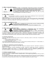
1.3.12 Safety guidelines for handling batteries


Never leave the battery close to a flame or fire. 
Use only insulated tools. 
Never use sulphuric acid or acid water to top up the electrolyte level. 

Danger 


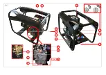
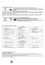
2. Description


Figure A 

1 Earth 

connection 

7 Recoil-starter 

13 Fuel 

filter 

Oil level gauge 

Circuit breakers 

14 

Air filter 

Oil filler plug 

Electrical sockets 

15 

Starter battery 

Fuel tank plug 

10 

Stop lever 

16 

Exhaust silencer 

Starting and shut-down key 

11 

Oil drain plug  


Solenoid valve 

12 

Oil filter 


Figure B 

Oil gauge 

Lower limit of gauge 

Screw 

Upper limit of gauge 

Oil drain plug  

Oil filter 


Figure C 

Fuel tank exit hose 

Input & return hoses for the fuel 
filter 

Fuel filter screw 


Figure D 

Nut for the air filter cover  

Wing nut 

Paper element 

Air filter cover 

Foam element  

Rubber gasket 


3. Preparation before use


3.1. Positioning the generating set for operation


Choose a site that is clean, well ventilated and sheltered from bad weather. 
Place the generating set on a flat, horizontal surface which is firm enough to prevent the set sinking down (under no circumstances 
should the set tilt in any direction by more than 10°). 
Store the additional supplies of oil and fuel within close proximity, whilst maintaining a certain distance for safety. 
 

3.2. Earthing the generating set


The generating sets supply electrical current when in operation: risk of electrocution. 
Connect the generating set to the ground at each use.


Danger


To connect the set to the ground: Attach a 10 mm

2

 copper wire to the set’s earth connection and to a galvanised steel earthing rod 

driven 1 meter into the ground. 


Summary of Contents for Diesel 6000 E

Page 1: ... původní poznámky Ε Ε χ χ ο ο χ χ η η α α ν ν η η η η ά α η ω η ιώ ή η ω ό M Ma an nu ue el l d d u ut ti il li is sa at ti io on n e et t d d e en nt tr re et ti ie en n N No ot ti ic ce e o or ri ig gi in na al le e Р Р д д ц ци ии и и и ж жи и и и N и и а ь у ия M Ma an nu ua al l d de e u ut ti il li iz za ac ci ió ón n y y m ma an nt te en ni im mi ie en nt to o T Tr ra ad du uc cc ci ió ón n...

Page 2: ...A O I 4 3 7 16 15 14 5 8 9 1 6 10 STOP 13 12 11 2 ...

Page 3: ...B C 1 3 2 4 5 6 1 2 3 ...

Page 4: ...D 1 3 4 5 6 2 ...

Page 5: ...t gases Do not use in a confined or poorly ventilated area 3 Stop the motor before filling with fuel 1 2 3 A Generating set model B Generating set output C Voltage D Amperage E Current frequency F Power factor Example of an identification plate G Protection rating H Generating set noise output I Generating set weight J Reference Standard K Serial number 1 3 Instructions and safety regulations Do n...

Page 6: ...ent connected to the outlets of the generating set must be interconnected with the ground of the set by a protection conductor This equipotentiality is performed if all the connecting cables of class I equipment are fitted with a PE protection conductor GREEN and YELLOW correctly connected to their patches to the generating set this protection conductor is not necessary for equipment of class II p...

Page 7: ...nd accidents involving or damage to the surrounding equipment and property If it is necessary to operate it inside a building the exhaust gases must be evacuated outside and adequate ventilation must be provided so that any people or animals present are not affected 1 3 8 Operating conditions The stated outputs of the generating sets are obtained under the reference conditions outlined in ISO 8528...

Page 8: ... plug 9 Electrical sockets 15 Starter battery 4 Fuel tank plug 10 Stop lever 16 Exhaust silencer 5 Starting and shut down key 11 Oil drain plug 6 Solenoid valve 12 Oil filter Figure B 1 Oil gauge 3 Lower limit of gauge 5 Screw 2 Upper limit of gauge 4 Oil drain plug 6 Oil filter Figure C 1 Fuel tank exit hose 2 Input return hoses for the fuel filter 3 Fuel filter screw Figure D 1 Nut for the air f...

Page 9: ...l If necessary fill up p Fill the fuel tank using a funnel while taking care not to spill the fuel Only use clean fuel without any presence of water Do not overfill the tank there should not be any fuel in the filler neck After filling always check that the fuel tank cap is properly closed If any fuel has been spilt ensure that it has dried and that all vapour have evaporated before starting the g...

Page 10: ... well depressed Press if necessary o Connect the devices to be used to the electrical sockets fig A No 9 of the generating set N B The SDMO generating sets are equipped with Schucco type sockets in exceptional cases it may be that some devices cannot be connected In such a case an adapter will be supplied freely on request by our sales office show proof of purchase 4 3 Switching off n Stop disconn...

Page 11: ... of limited use drain the oil every year at the latest 7 Maintenance procedures Before carrying out any maintenance operation switch off the generating set disconnect the cap s of the spark plug s and disconnect the starter battery if fitted Warning Only use original parts or equivalent parts risk of damage to the generating set 7 1 Checking bolts nuts and screws To prevent faults or breakdowns ca...

Page 12: ... No 3 q Remove the fuel filter fig A No 13 r Fit a new fuel filter s Refit the retaining clamp of the fuel filter and tighten the screw t Refit the hoses clamps u Fill up with fuel wipe away any traces with a clean cloth and check for leakage 7 5 Cleaning the air filter Never use petrol or solvents with a low flash point for cleaning the air filter element risk of fire or explosion Important n Rem...

Page 13: ...ating set apply an anti rust product onto the damaged areas s Cover the generating set with a drop cloth to protect it from dust and store it in a clean dry location 9 Troubleshooting Problems Probable causes Possible solutions Engine does not start Load connected to the generating set during start up Disconnect the load Air filter fig A No 14 blocked Clean the air filter see Cleaning the air filt...

Page 14: ...4 10 16 5 6 9 20 10 7 2 5 12 16 5 4 10 25 3 6 9 25 10 7 4 10 16 5 6 9 25 3 10 7 32 10 7 25 3 35 2 40 16 5 35 2 50 0 50 16 5 35 2 50 0 63 25 3 50 0 70 2 0 12 EC Declaration of conformity Name and address of manufacturer SDMO 12 bis rue de la Villeneuve CS 92848 29228 BREST CEDEX 2 FRANCE Description of the equipment Generating set Make SDMO Type Diesel 6000 E Name and address of the person authoris...

Page 15: ...1 2 3 4 Э 5 6 7 8 Х 9 10 Х 11 12 1 1 1 1 2 1 2 3 1 2 3 A B C D E F G H I J K 1 3 1 3 1 Э Э Э ...

Page 16: ...1 3 2 Э 1 3 3 Э 1 a I PE Ы II Э 60245 4 b 30 A 1 2 1 a 1 1 ...

Page 17: ...1 3 4 1 3 5 1 3 6 В В 1 3 7 Э 1 3 8 ISO 8528 1 2005 9 100 9 25 C 298 K 9 30 Х 4 10 C 1 100 1 3 9 Э 1 3 10 ...

Page 18: ...1 3 11 В Х 1 3 12 2 Ри A 1 7 13 2 8 14 3 9 15 4 10 16 5 11 6 Э 12 Ри B 1 3 5 2 4 6 Ри C 1 2 3 Ри D 1 3 5 2 4 6 3 3 1 10 ...

Page 19: ...3 2 Э 10 2 1 3 3 Х 30 n A 2 B 1 o B 2 B 3 p q r s 3 4 За ив а ива n A 4 o p q 3 5 n D 1 2 o D 3 D 4 5 p q 3 6 ...

Page 20: ...4 Э 4 1 n З o p A 5 15 2 q 4 1 1 n A 5 B o A 6 I p A 7 q r A 6 O 4 2 3 n A 8 o A 9 SDMO Schucco 4 3 В n A 9 o 1 2 p A 5 A A 10 A 5 5 1 В Э 5 2 ...

Page 21: ...6 6 1 6 2 Э 1 1 10 1 2 50 1 6 250 1 500 7 7 1 n o 7 2 В З n A 11 A 3 o p Х q r ...

Page 22: ...7 3 n A 3 11 o B 5 p B 6 q r s t Х u 7 4 n 1 C 1 2 o C 2 p C 3 q A 13 r s t u 7 5 n D 1 2 o D 3 4 5 1 2 1 2 p q D 6 r ...

Page 23: ...7 6 7 7 n o p 8 Х n З o p З З q r s 9 У A 14 З A 13 З A 15 З A 8 A 9 ...

Page 24: ...0 16 6 9 2 5 12 10 7 4 10 16 5 6 9 20 10 7 2 5 12 16 5 4 10 25 3 6 9 25 10 7 4 10 16 5 6 9 25 3 10 7 32 10 7 25 3 35 2 40 16 5 35 2 50 0 50 16 5 35 2 50 0 63 25 3 50 0 70 2 0 12 SDMO 12 bis rue de la Villeneuve CS 92848 29228 BREST CEDEX 2 FRANCE SDMO Diesel 6000 E G Le Gall SDMO 12 bis rue de la Villeneuve CS 92848 29228 BREST CEDEX 2 FRANCE G Le Gall 2006 42 EC 2006 95 EC 2004 108 EC 01 2010 G L...

Reviews: