2.
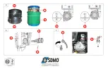
Description
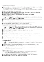
Figure A
1
Earth connection
6
Engine fuel tap
11
Circuit breaker
2
Oil filler gauge plug
7
Air filter
12
Electrical sockets
3
Oil draining screw
8
Choke
13
Exhaust silencer
4
Fuel tank plug
9
Start and stop control
5
Screen filter
10
Recoil starter handle
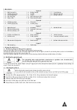
Figure B
1
Oil draining screw
3
Filler neck
2
Oil filler gauge plug
4
Oil filling plug
Figure C
1
Engine fuel tap
4
Enclosure
7
Sediment bowl
2
Enclosure fixing screw
5
Sediment bowl cover
3
Enclosure locking nuts
6
Seal
Figure D
1
Air filter cover fasteners
3
Paper element
5
“Normal” position
2
Air filter cover
4
Foam element
6
“Low temperatures” position
Figure E
1
Spark arrester fixing screw
2
Spark arrester
3
Exhaust silencer protection
Figure F
1
Spark plug cap
2
Spark plug
3.
Preparation before use
3.1.
Positioning the generating set for operation
Choose a site that is clean, well ventilated and sheltered from bad weather.
Place the generating set on a flat, horizontal surface which is firm enough to prevent the set sinking down (under no circumstances
should the set tilt in any direction by more than 10°).
Store the additional supplies of oil and fuel within close proximity, whilst maintaining a certain distance for safety.
3.2.
Earthing the generating set
The generating sets supply electrical current when in operation: risk of electrocution.
Connect the generating set to the ground at each use.
Danger
To connect the set to the ground: Attach a 10 mm
2
copper wire to the set’s earth connection and to a galvanised steel earthing rod
driven 1 meter into the ground.
3.3.
Checking the oil level
Before starting the generating set, always check the engine oil level.
Top up with the recommended oil (see § Characteristics) using a funnel, up to the top limit of the gauge.
Important
Remove the oil filler gauge plug (fig. A - No. 2 & fig. B - No. 2) by unscrewing it, and wipe the gauge.
Insert the oil filler gauge plug into the filler neck (fig. B - No. 3) without screwing it, then remove it.
Visually check the level and top up if necessary.
Screw the oil filler gauge plug back fully into the filler neck.
Wipe off excess oil with a clean cloth, check that there are no leaks.
Summary of Contents for PERFORM 3000
Page 2: ...A 8 6 4 5 13 3 9 11 12 2 1 10 7...
Page 3: ...B C 5 6 7 3 4 1 2 2 3 1 4 1...
Page 4: ...D E F 3 4 5 6 2 3 1 X 1 2 2 1...
Page 75: ...1 2 3 4 5 6 7 8 9 10 11 12 13 1 1 1 1 2 1 2 3 1 2 3 A H B I C J D K E L F M G 1 3 1 3 1...
Page 76: ...1 3 2 1 3 3 1 a I PE II 60245 4 b 30 A 1 2 1 a 1 1...
Page 80: ...4 3 A 12 1 2 A 9 OFF O A 6 C 1 5 5 1 5 2 6 6 1 6 2 1 50 100 200 7 7 1...
Page 82: ...7 6 E 1 E 2 E 3 7 7 F 1 F 2 1 2 X 0 7 0 8 1 8 1 4 7 8 8 A 6 C 1 A 6 0 F 2 15 A 10...
Page 116: ...1 3 2 1 3 3 1 I PE II IEC 60245 4 30mA 1 2 1 1 1...
Page 120: ...6 2 1 1 50 1 100 1 200 7 7 1 7 2 A 3 B 1 A 2 B 2 B 4 7 3 A 4 A 5...
Page 122: ...7 8 8 A 6 C 1 A 6 0 F 2 15 ml A 10 9 A 9 O OFF I ON A 6 A 7 F 2 D 6 A 11 A 12...

