3.4.
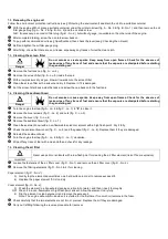
Checking the fuel level
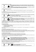
Filling up with fuel must be carried out when the engine is stopped and in accordance with
safety instructions (see. § Filling with fuel).
Danger
Unscrew the fuel tank cap (diag. A - no. 4).
Visually check the level of fuel. If necessary, fill with fuel:
Fill the fuel tank using a funnel, taking care not to spill any fuel.
Use only clean fuel, free from water.
Do not overfill the tank (there should not be any fuel in the filler neck).
After filling, always ensure that the filler cap is properly tightened.
If any fuel has been spilt, make sure that it has dried and that any vapours have cleared before starting up the
generating set.
Important
Screw the fuel tank plug carefully back on.
3.5.
Checking the air filter
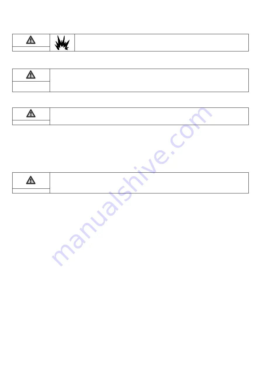
Never use petrol or solvents with a low flash point for cleaning the air filter element (risk of fire or explosion).
Important
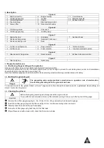
Loosen the air filter cover fasteners (fig. D - No. 1).
Remove the air filter cover (fig. D - No. 2) then the filtering elements (fig. D - No. 3 & 4) and visually check their condition.
Clean or replace the elements if necessary (see. § Cleaning the air filter).
Refit the filtering elements and the air filter cover.
Tighten the air filter cover fasteners.
Position the air filter to the "Normal" operating position.
4.
Using the generator set
Before use:
- find out how to stop the generating set in an emergency,
- ensure you fully understand all the controls and manoeuvres.
To stop the generating set in an emergency, switch the control or the on/off key to "OFF" or "O".
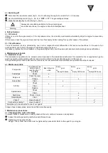
Warning
4.1.
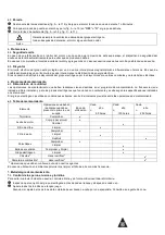
Starting procedure
Check that the generating set is connected to the ground (see § Earthing the generating set).
Select the position of the air filter (fig. A - no. 7) in accordance with the operating conditions:
- for normal temperatures, select the “Normal” position (fig. D - no. 5),
- in the event of the risk of ice, select the “Low temperatures” position (fig. D - no. 6).
Turn the engine fuel tap (fig. A - no. 6 & fig. C - no. 1) to "
I
I
”
”
to open it.
Bring the choke lever (fig. A - no. 8) to "I".
N.B: Do not use the choke when the engine is hot or when the atmospheric temperature is high.
Set the on/off switch (fig. A - no. 9) to
"
"
O
O
N
N
"
" or
"
"
I
I
"
".
Pull the recoil starter handle once (fig. A - no. 10) gently until it engages and let it return gently to its initial position.
Then give the recoil starter a swift and strong pull to start the engine.
Gently bring the choke lever to "O" and wait for the engine temperature to rise before using the generating set.
If the engine does not start, repeat the operation until the engine starts by gradually opening the choke.
4.2.
Operation
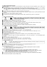
When the running speed of the generating set has stabilised (approximately 3 minutes):
Check that the circuit breaker (fig. A - No. 11) is pushed in. Press on it if necessary.
Connect the appliances that are to be used to the electrical sockets (fig. A - No. 12) of the generating set.
Summary of Contents for PERFORM 3000
Page 2: ...A 8 6 4 5 13 3 9 11 12 2 1 10 7...
Page 3: ...B C 5 6 7 3 4 1 2 2 3 1 4 1...
Page 4: ...D E F 3 4 5 6 2 3 1 X 1 2 2 1...
Page 75: ...1 2 3 4 5 6 7 8 9 10 11 12 13 1 1 1 1 2 1 2 3 1 2 3 A H B I C J D K E L F M G 1 3 1 3 1...
Page 76: ...1 3 2 1 3 3 1 a I PE II 60245 4 b 30 A 1 2 1 a 1 1...
Page 80: ...4 3 A 12 1 2 A 9 OFF O A 6 C 1 5 5 1 5 2 6 6 1 6 2 1 50 100 200 7 7 1...
Page 82: ...7 6 E 1 E 2 E 3 7 7 F 1 F 2 1 2 X 0 7 0 8 1 8 1 4 7 8 8 A 6 C 1 A 6 0 F 2 15 A 10...
Page 116: ...1 3 2 1 3 3 1 I PE II IEC 60245 4 30mA 1 2 1 1 1...
Page 120: ...6 2 1 1 50 1 100 1 200 7 7 1 7 2 A 3 B 1 A 2 B 2 B 4 7 3 A 4 A 5...
Page 122: ...7 8 8 A 6 C 1 A 6 0 F 2 15 ml A 10 9 A 9 O OFF I ON A 6 A 7 F 2 D 6 A 11 A 12...


