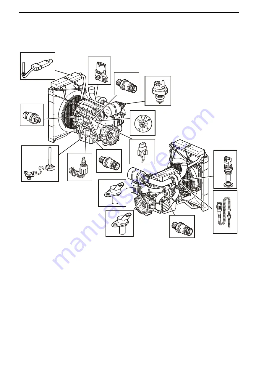
Location of Sensors
TWD1643GE
P0002059
15
14
13
11
12
1
2
3
4
5
10
9
8
7
6
1 Coolant level sensor, in expansion tank
9 Oil level and temperature sensor
2 Charge air pressure and temperature
sensor
10 Crankhouse pressure sensor
3 Oil pressure sensor
11 Coolant temperature sensor
4 Airfilter indicator
12 Exhaust temperature sensor
5 Aux stop
13 Piston cooling pressure sensor
6 Fuse
14 Flywheel position and engine speed sensor
7 “Water in fuel” sensor
15 Camshaft position sensor
8 Fuel pressure sensor
16 Solenoid valve, drainage, water trap (optional), not shown
in illustration
Maintenance
56
7748681 12-2011
184/297
Summary of Contents for R570U
Page 1: ...User and maintenance manual for generating sets R570U 33504081501NE_1_1 ...
Page 15: ...Alternator Cabinet Figure 1 3 Examples of identification plates 13 297 ...
Page 18: ...Sockets voltage 208 120V 16 297 ...
Page 125: ...9 Appendix 9 1 Appendix A Engine user and maintenance manual 123 297 ...
Page 126: ...124 297 ...
Page 128: ...126 297 ...
Page 129: ...OPERATOR S MANUAL Generating set and industrial engines 16 liter EMS 2 127 297 ...
Page 159: ...157 297 ...
Page 218: ...216 297 ...
Page 220: ...218 297 ...
Page 222: ...7748681 English 12 2011 220 297 ...
Page 223: ...9 2 Appendix B Alternator user and maintenance manual 221 297 ...
Page 224: ...222 297 ...
Page 226: ...224 297 ...
Page 250: ...www leroy somer com 248 297 ...
Page 261: ...Installation and maintenance R250 A V R 4067 en 2009 05 b LEROY SOMER 11 259 297 ...
Page 281: ...2012 03 e LEROY SOMER 19 Installation and maintenance R 450 AVRs 4531 en 279 297 ...
Page 282: ...www leroy somer com 280 297 ...


