Vigilant User Manual
15/232
6.
Design
6.1.
External appearance
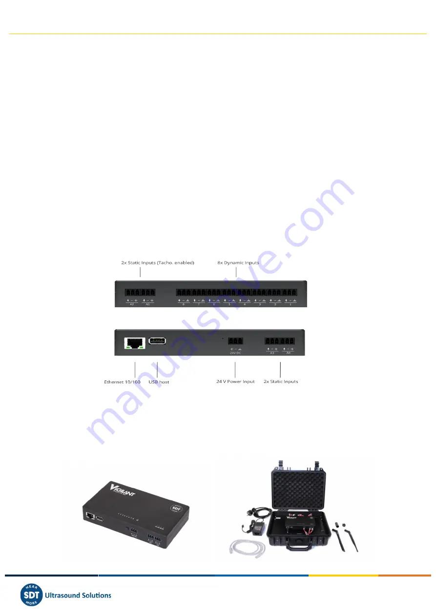
At the front and back sides of
Vigilant
several pluggable terminal blocks allow connecting wires both
for sensor signals and power supply. All these terminals are to be connected only to SELV-LPS (safety
low-voltage) lines.
Vigilant
also has an RJ45 port for Ethernet communications (100Base-TX). The Ethernet port is to be
connected to indoor routed networks exclusively.
Next to the RJ45 port, the case includes a USB connector of A-type that can be used as a power supply.
The port can’t be used
to interact with VIGILANT.
On the top of the instrument, several LED indicators give information about the device’s state and the
signals being read. The meaning of the colors used is described below.
The following chapters contain some images with more detailed information about the
Vigilant
and its
hardware.
6.2.
Standard model
The
Vigilant
has 8 main dynamic analog inputs (high-frequency sampling rate) and 4 auxiliary inputs
(low-frequency), for static analog sensors or tachometers.
The standalone Vigilant system is designed for permanent mounting on DIN rail. The mobility Vigilant
system embeds the same main functions as Vigilant Permanent while offering various wireless
possibilities (4G, WIFI (access point or client), etc.)
. It’s packaged in rugged, custom waterproof case
designed to travel to off-site assets. It can be installed on critical assets to closely monitor until planned
shutdown.


