Vigilant User Manual
26/232
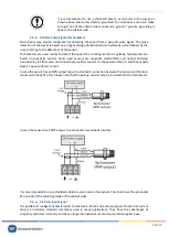
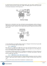
To acquire this type of signals from the main primary inputs, user must connect a resistance on the
terminals to convert the current signal into a voltage. The following graphs show the wiring required
for both active and passive 4-20 mA loop sensors:
Many sensors in the market can use the current loop for powering themselves, without needing any
other power source (
passive loop
). However, the terminals of the
Vigilant
do not have the possibility
of powering the sensors in that way. Thus in between the sensor and
Vigilant
must add an external
power source:
It is recommended to use a shielded cable to avoid noise in the signals. The shield must be grounded
at one side of the cable (typically at the cabinet side).
9.4.4.
Digital Inputs
Main inputs can be configured as a digital input. This means the channel will measure a value of 1
(true) or 0 (false) depending on the signal’s DC voltage. A hysteresis applies close to this setting value.
The user can configure both DC voltage and hysteresis.
As an example, if the threshold is set up in 1 V, and hysteresis is defined in 0.1 V, the input will measure
a value of 1 when the DC voltage of the input goes above 1.1 V. And then it will measure a value of 0
when the voltage goes below 0.9 V.
9.4.5.
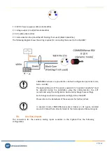
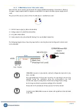
CONMONSense Sensor 0-10 V (dynamic mode)
Note that the sensor needs an external 24V DC supply capable of delivering at least 40 mA. Utilizing
the power supply supplied with the Vigilant is acceptable or a separate dedicated power supply can be
used.
The pinout of the sensor, extracted from the datasheet, is recalled hereunder.

