Vigilant User Manual
28/232
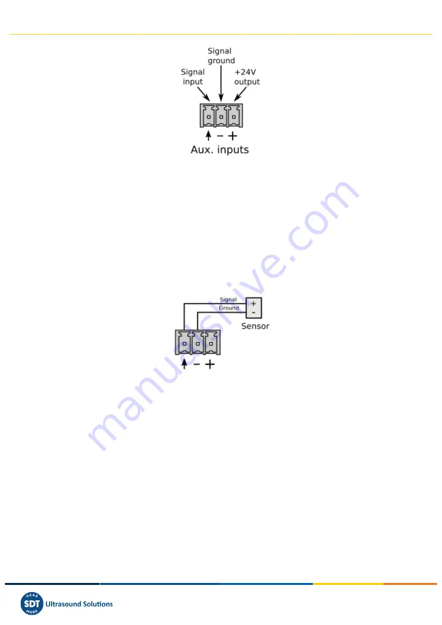
The auxiliary inputs admit voltage signals in the range of ±24 V and design to read analog signals at
slow rates.
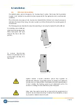
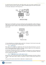
As it is shown in the image, all the auxiliary inputs connectors include a signal ground (0V reference)
terminal. All those terminals, labeled as “
-
”, are connected internally to the circuit 0V reference, and
they are also in electrical contact with the negative terminal of the power input.
The auxiliary inputs connectors also have a terminal with a +24 V power output, available for powering
external sensors or peripherals. All those terminals, labeled as “+”, are connected internally to the
c24 V power input.
A typical connection for a generic sensor to these inputs, with self is shown in the following picture:
This scheme is valid for any kind of sensor with external power supply and voltage output (analog or
digital).
In the following sections will show the typical connection between different kinds of sensors and the
auxiliary inputs.
9.5.1.
Periodic Pulse Signal (Tachometer)
Some of the auxiliary inputs may also be configured for detecting the speed from a periodic pulse
signal. The pulse detection of the signal is based on a trigger voltage (threshold) and a hysteresis value
defined by the user.
Tachometers are used mainly to detect the speed of a rotating machine. Typically, tachometers are
based on proximity sensors. Most used sensors are magnetic (Hall effect) and optical (infrared
transducers). In either case, most industrial proximity sensors can be powered at 24 V, and they can
be powered from the +24 V output terminal.
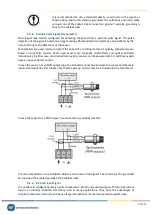
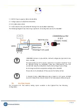
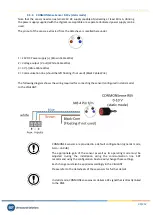
The connection between the auxiliary inputs and a tachometer with analog or digital inputs would look
like this:

