Vigilant User Manual
82/232
Number
of
registers
Number of Modbus
Input
registers (16bit) occupied by the component’s block of data or
by the different variables.
Number
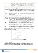
Modbus-TCP address or register number assigned to the variable.
The
Edit
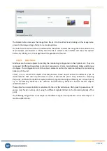
buttons of each component are used to manually set the initial Modbus-TCP address of the
components. Then the system automatically defines the register number (Modbus-TCP
Input
register
addresses) for each variable, considering the initial address of the component and the number of
registers they occupy. This number of registers are shown on the list for each variable, along with its
data type and the final Modbus-TCP address assigned.
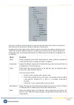
The initial Modbus-TCP address numbers of the different components can also be assigned
automatically by using the
Auto-assign registers
button. In the case of selecting
Only empty records
those components with no address number assigned will be set only. In case of
All
is selected the
system will redefine automatically all the address numbers, assigning new ones even to those that
were previously defined.
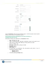
Once the Modbus addresses or register numbers are defined for the different variables, they will be
accessible by other devices using these connection properties:
-
Host
: IP address in the local network
-
Port number
: 502
-
Slave ID
: 1
-
Register type
:
Input
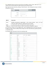
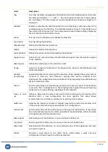
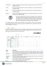
The following table describes the different types of variables that include each component.
Component
Variable
Description
Machines
Speed
This variable provides the speed measurement of the machine. This
value can be read by the system using a static or dynamic input channel,
by OPC or Modbus measurement or by a
Formula
. It can also be defined
as a fixed value defined in the configuration.
Load
This variable provides the load value of the machine. This value can be
read by the system as an input channel, by OPC/Modbus measurement
or by a
Formula
. It can also be defined as a fixed value defined in the
configuration.
State
Provides the status of the machine. It gives the number assigned to the
state, as defined on the configuration of the
Machine
.
Alarm
Provides the alarm condition of the
Machine
. It can take one of these
numbers: 0 (no alarm), 1 (warning), 2 (alert), 3 (danger). The
Machine
takes the higher alarm condition of any of their measurements.
Error
Provides a number different from 0 in case an error is found on any of
the measurements of the
Machine
. See Error codes for more
information.
Points
Vbias
Provides the bias voltage value of the input channel associated with the
corresponding
Measurement
Point
.

