background image


Vigilant User Manual 

229/232 


19.


Appendix D 

19.1.


Keyboard Shortcuts 

Key 

Action 

General


escape 

Close modal window (one level). 

Show this panel. 

Show alarm log. 

Open or close the sidebar. 

Desktop


ctrl + d 

Add a new desktop. 

Select the next desktop (in cycle). 

Enter layout editor. 

shift + d 

Select previous desktop (in cycle). 

shift + tab 

Focus previous widget (in cycle). 

tab 

Focus next widget (in cycle). 

Layout Editor


escape 

Exit layout editor. 

Move the desktop tab to the right. 

shift + r 

Move the desktop tab to the left. 

Forms


arrowdown 

Move form select list down. 

arrowup 

Move form select list up. 

enter 

Accept form. 

escape 

Cancel form. 

shift + tab 

Focus on the previous form element. 

space 

Toggle checkbox or select option. 

tab 

Focus on the next form element. 

Any Widget


Open widget configuration. 

delete 

Delete widget. 

Open or close widget info panel. 

Space 

Maximize or minimize widget. 

Summary of Contents for Vigilant

Page 1: ...info sdtultrasound com SDT North America 7677 County Road 2 Cobourg ON K9A 0X4 Canada Phone 1 800 667 5325 1 905 377 1313 hearmore sdtultrasound com www sdtultrasound com USER MANUAL Version 4 2022 S...

Page 2: ...ent 17 7 2 Additional specifications with the Mobility case 18 8 Installation 19 8 1 Mechanical assembly 19 9 Electrical installation 21 9 1 Connectors 21 9 2 Power supply 21 9 3 Ground connection 22...

Page 3: ...bus master 78 12 8 Modbus slave 81 12 9 OPC 83 12 9 1 About OPC 83 12 9 2 OPC UA client in Vigilant 83 12 9 3 OPC endpoints 84 12 9 4 OPC nodes 85 12 10 Techniques 88 12 11 Units 89 12 12 Images 91 12...

Page 4: ...ation 165 13 5 2 Display 165 13 5 3 Types of graphs 166 13 5 4 Access to trends chart 167 13 6 Trends 167 13 6 1 Configuration 167 13 6 2 Display 169 13 6 3 Zoom tools 170 13 6 4 Time range 170 13 6 5...

Page 5: ...Maintenance 215 14 1 Relevant aspects 215 14 2 Periodic inspections 215 14 3 Reboot 215 14 4 Rescue mode 216 14 5 Micro SD card maintenance 216 14 6 Replacement of internal components 217 14 6 1 Acces...

Page 6: ...s or inconsistencies that may contain in this manual nor for indirect and consequential damages either including any lost profits or savings resulting from the use or application of this equipment Inf...

Page 7: ...5 B 1190 Brussels Belgium Email info sdtultrasound com 2 2 Installation assistance If you experience a problem with a Vigilant unit please review the information contained in this manual You can also...

Page 8: ...semblies and supplies used to manufacture the product complies with the European Union 2011 65 EU directive on the restriction on using dangerous substances in manufacturing electronic and electrical...

Page 9: ...ing address SDT North America Toll Free 1 800 667 5325 Phone 1 905 377 1313 7677 County Road 2 Cobourg ON K9A 0X4 Canada Email info bevigilant io Web page https bevigilant io SDT International Phone 3...

Page 10: ...and contact your distributor or SDT for assistance Be sure that main power is off and will stay off until the installation work ends Check that the equipment is voltage free by using a voltage tester...

Page 11: ...cations at altitudes up to 2000 meters See Specifications for environment specifications applied for the equipment 4 4 ATEX The equipment has not been designed to be installed in potentially explosive...

Page 12: ...ection may result in an electrical risk and cause the equipment to work in an unfavorable operating condition See Electrical installation for the wiring details about how to connect the power supply a...

Page 13: ...ot use the equipment if it presents damage after transportation or storage due to improper or careless handling Please place it in a location free from direct sunlight high temperature or humidity or...

Page 14: ...ling any software With that web interface the user can configure and access all data being measured in the unit along with all the types of graphs required for its visualization and analysis trends sp...

Page 15: ...ndicators give information about the device s state and the signals being read The meaning of the colors used is described below The following chapters contain some images with more detailed informati...

Page 16: ...is on and ready Power supply is ok Solid red Unit is in rescue mode Ethernet connector Yellow or green Link Activity Input ports Any type Off The input channel is either disabled or if enabled it is p...

Page 17: ...ge capacity GB 4 Micro SD card format ext3 Database system SQLite Network interface Ethernet 10 100 Communication DHCP static configuration Default IP access 192 168 0 150 Industrial communication MOD...

Page 18: ...ncy extraction Crest Factor Kurtosis Peak phase Smax Available filters Butterworth Bessel Chebyshev Number of averages 1 up to 32 Overlap 0 up to 99 Bearing database Included 50 k bearing references W...

Page 19: ...gilant from the DIN rail To install the unit on a DIN rail align it with the top edge press firmly downwards and push forward the lower end into position To remove the unit press firmly on top downwar...

Page 20: ...corresponding components within the enclosure Direct sunlight and high ambient temperatures should be avoided It is recommended to separate the unit from any external heat source that could cause hig...

Page 21: ...age For Vigilant maximum voltages range 24V DC That applies both for power and signal connections including all inputs Vigilant also has a RJ45 port on the left part of the front of the case used for...

Page 22: ...d connection All those terminals are connected in between and in turn both to the Vigilant case and the DIN rail clip Grounding provides a safe electrical operating system and helps avoiding potential...

Page 23: ...ion ground and the DIN rail where the Vigilant is supported The DIN rail can be grounded connecting it directly to the ground bus as shown above or by using a rail grounding terminal shown below 9 4 M...

Page 24: ...The signal terminal of the main inputs Vigilant connect to a current source of about 5 5 mA activated for powering ICP IEPE transducers like many sensors A typical connection between the high speed i...

Page 25: ...tic Hall effect and optical infrared transducers In either case most industrial proximity sensors can be powered at 24 V and they usually have an open collector output In case the sensor has an NPN ou...

Page 26: ...de of the cable typically at the cabinet side 9 4 4 Digital Inputs Main inputs can be configured as a digital input This means the channel will measure a value of 1 true or 0 false depending on the si...

Page 27: ...of the sensor equivalent to apparent sensitivity must be adjusted during the installation using the communication line SDT recommend using the configuration box to easily change these settings Each c...

Page 28: ...picture This scheme is valid for any kind of sensor with external power supply and voltage output analog or digital In the following sections will show the typical connection between different kinds...

Page 29: ...gured to measure 4 20 mA current loop signals This kind of current loop is an industry standard used in many applications They have the advantages of simplicity and noise immunity and have a large int...

Page 30: ...hould be left floating if not used Black Cable Wire The following diagram shows the wiring required for connecting the sensor configured in static mode to the VIGILANT CONMONSE sensors are provided in...

Page 31: ...the way to access the configuration interface By default the user interface will show the Dashboard application Connect the Vigilant to your device or network using an Ethernet cable A quick user inst...

Page 32: ...w or hide on the left of the screen a panel with the configuration Tree In the main user interface this structure will show the system s measurement configuration When instead of the Dashboard shows M...

Page 33: ...alarms relate to system alarm such as measurements that can be out of user specifications For example this kind of alarms could be useful to indicate if the current measurement is beyond above the spe...

Page 34: ...able applications The Dashboard application is shown by default when accessing the system 10 3 3 Exception indicator In case a warning system event or exception occurs a red bell shaped icon will appe...

Page 35: ...e full status page of the system configuration that is also available in section System See Status 10 3 6 Help button The Help button opens the user manual in a separated tab in PDF format Please note...

Page 36: ...ashboard settings Import desktops Import a JSON file dat containing the desktop layout information and unit preferences Load the dashboard settings Rename tags This menu allows changing machine s tags...

Page 37: ...ase unit To add a new unit preference select the left control property and then the appropriate unit in the right control Then click on Add Update to include it in the list and it will be ready to be...

Page 38: ...the Vigilant until the button from the toolbar is used Some fields are guided by a help text in grey color and on the field itself when it is blank They typically show an example or a tip about how to...

Page 39: ...components of the configuration interface are defined using expressions or formulas that allow to build flexible rules to define how the system behaves In particular these expressions are used to def...

Page 40: ...st the corresponding operator will be inserted automatically on the expression field The system checks automatically if the syntax of the expression is correct In case they are not the editor will sho...

Page 41: ...is provided in the units defined on the corresponding field Load_change Returns the load change of the Machine It is calculated by the difference in absolute value between the current Machine load me...

Page 42: ...ified as the e_str plus the Storage strategy index number This identifier is shown on the Storage strategies list For each Storage strategy these variables provide the time elapsed in seconds between...

Page 43: ...ed with the different alarms are the same as for the Alarm variable described on the previous page Ok 0 Warning 1 Alert 2 Danger 3 Pulse_train_point fr eq error This type of variable is set to 0 when...

Page 44: ...the same value and it returns FALSE otherwise The greater than or equal to operator returns TRUE if its left hand operand is greater than or equal to its right hand operand and it returns FALSE other...

Page 45: ...ression That number or expression must be enclosed in brackets after the Sin operator e g sin 9 sin a b The function assumes that the number or result of the expression enclosed in brackets is in Radi...

Page 46: ...n its writing When evaluating conditions a resulting value from the expression different of 0 is equivalent to True A resulting value equal to 0 is equivalent to False It is also possible to include F...

Page 47: ...the second operand is no longer evaluated With all of that in mind it is easy to generate concatenated expressions of the type if else if else For example consider this expression val1 rms 0 1 or val2...

Page 48: ...terface a vertical menu shows the different system settings options available Icon Description This button reboots the unit After clicking on it a modal window will ask the user to confirm or cancel t...

Page 49: ...s and records stored in the unit for each machine and allows it to erase them within a time range It also allows the user to rebuild the database from the data blocks or records stored Backup Shows th...

Page 50: ...user Model Shows the model of the Vigilant unit Hardware version This field shows the version of the hardware Firmware version This field shows the version of the firmware installed on the unit Hostn...

Page 51: ...can be changed on the Time settings see Time Local Time Shows the local date and time The unit reads the location from the device that shows the interface Uptime This field indicates the time elapsed...

Page 52: ...also allows users to edit the Machine Configuration but not to change the System Settings options Guest This role allows the user to acknowledge and remove alarms It also allows the user to view the d...

Page 53: ...e created After entering the name of the new user and pressing on the OK button the new user will be created with the user configuration previously copied The Export and Import buttons on the Users fo...

Page 54: ...he DNS to convert the host names to the IP addresses of the web servers DNS2 Defines the secondary DNS address This menu is basic to set up the device and be able to access it in the future If you are...

Page 55: ...he time of the unit with the NTP server Test NTP This button provides a connection test with the NTP server Only appears if Enable NTP checkbox has been marked Local Sync Synchronizes the time of the...

Page 56: ...Users can customize emails with a user defined message This E mail notifications form includes the possibility of sending a test email to verify that the email addresses and the network configuration...

Page 57: ...more than one email per day even if more critical alarm levels are reached It will always wait a minimum of 24h before sending new emails On the other hand the system will only send a single email for...

Page 58: ...Sync server so a Rsync client is required to use this service See https en wikipedia org wiki Rsync for more information Similarly to FTP make sure to use binary format in order to upload and download...

Page 59: ...by using the RSync or FTP services at least the files included in the folders Snapshots and Long Waveforms this last one only in case long waveforms processing modes are configured These folders conta...

Page 60: ...ard with the selected file format Changes in this menu will only apply after rebooting the system 11 10 Records This menu shows the usage of the device internal storage memory and how it is shared bet...

Page 61: ...d just before shutting down the system This database allows the system to quickly restore the trends from the RAM when restarting the unit This Records form allows the reconstruction of the SQL databa...

Page 62: ...on the Update database button at the top right of the form rebuilds the internal MySQL database that includes the trends of the scalar measurements Index db This is done by reading all the Snapshot f...

Page 63: ...ces For this purpose this form allows uploading spreadsheet files with lists of bearings to be added to the database of the device The format of the spreadsheets must be CSV it is a standard format th...

Page 64: ...responding license will be activated 11 14 Upgrade firmware This form shows the current firmware version of the Vigilant unit and allows upgrading it to the latest version available See the chapter ab...

Page 65: ...tions allow loading beta releases of the firmware Only SDT personnel can change this setting The latest firmware can be downloaded at http ftp sdt be pub Products VIGILANT Vigilant Firmware Do not dis...

Page 66: ...ent settings will be lost Clear Clears the Monitoring configuration deleting all configured settings machines points processing modes sensors etc The Monitoring configuration of the unit gets complete...

Page 67: ...the System configuration settings into a db file called System plus the current data and time i e system_2021_04_03_6 45 db Import Imports into the VIGILANT unit a System configuration file selected...

Page 68: ...s to be done step by step in descending order from the inputs to the definition of the Machines Option Description This button applies the changes made into the configuration database to the Vigilant...

Page 69: ...its Sets the properties and units available on the system Images Defines the images available on the system to be assigned to a machine Machines Configures the Machines to be monitored with the VIGILA...

Page 70: ...tion database However they will not be applied into the Vigilant until the configuration errors are checked and the Apply configuration button is pressed 12 3 Sensors This section configures the senso...

Page 71: ...ations of CONMONSENSE 0 10 V Name CONMONSense_60dB Others non mandatory fields description manufacturer model serial number do not mater and you can fill them with whatever you think useful for your n...

Page 72: ...nsor provides a static or a dynamic signal Output Type Sets the type of output provided by the sensor In most cases it will be voltage but some sensors provide current outputs or are resistive sensors...

Page 73: ...ting it to the corresponding units using the Sensitivity defined 12 4 Inputs This section defines the configuration of the inputs By clicking on this option the interface shows the inputs list By clic...

Page 74: ...ut mode Hysteresis Sets a hysteresis around the threshold voltage that triggers the pulse detection For example a hysteresis value set at 0 1 V and threshold set at 1V will make the system detect the...

Page 75: ...he name of the new rolling bearing that the configuration of the one selected will be copied into By pressing the Delete button the interface will ask to confirm if the bearing must be deleted By clic...

Page 76: ...f the ball spin frequency of the bearing BPFO Sets the value of the ball pass frequency of the outer race of the bearing BPFI Sets the value of the ball pass frequency of the inner race of the bearing...

Page 77: ...ts can be assigned to dynamic points and are visualized on the Spectrum widgets of the Dashboard When selecting this option the interface will show the list of Fault frequencies defined on the unit By...

Page 78: ...times the RPM defined for the point If Use Order checkbox is not checked the user can select either CPM or HZ units to define the frequency Nb of harmonics Sets the number of harmonic lines to show o...

Page 79: ...address of the device that will act as Modbus server Port Number of TCP port that the server has reserved for Modbus communications By default the port number is 502 Slave Id Slave number of the serve...

Page 80: ...Modbus register Box unchecked indicates no swapping Word swap Swaps the position of 2 words 16 bits each one in a 32 bit data type Box unchecked indicates no swapping Read value Executes a single read...

Page 81: ...ts Clicking on the icon at the left of each component the interface will show the sub components These sub components are the variables that will be accessible by any external devices using Modbus TCP...

Page 82: ...they will be accessible by other devices using these connection properties Host IP address in the local network Port number 502 Slave ID 1 Register type Input The following table describes the differ...

Page 83: ...s the evolution of OPC Classic standard OPC UA is a cross platform industrial communication protocol It is open source service oriented and provides rich information models with all the characteristic...

Page 84: ...ng to a CSV file both OPC Endpoints and Nodes by using the Export and Import buttons 12 9 3 OPC endpoints The OPC configuration menu shows at the top of the interface the list of external OPC Endpoint...

Page 85: ...od for updating the values of the Nodes that belong to the Endpoint and are configured to execute Read services Node reading period Write period Period for updating the values of the Nodes that belong...

Page 86: ...s the Node unequivocally within the unit It can contain numbers upper and lower characters Special characters or blank spaces are not allowed Description Optional description of the Node content Endpo...

Page 87: ...scription Service Select Read from the pull down menu to use the read service that provides the OPC UA protocol Factor Factor to be applied to the data read by the Node This factor value will be multi...

Page 88: ...down menu to use the write service that provides the OPC UA protocol This service allows the writing of data into the Node being configured Data type Selects the type of data that is allowed to be wr...

Page 89: ...ower characters Special characters or blank spaces are not allowed Description This field allows the user to include a description of the Technique 12 11 Units This option defines the Properties and U...

Page 90: ...erty unequivocally It can contain numbers upper and lower characters Special characters or blank spaces are not allowed Label Text that will be used on the Dashboard to identify the Property Integrate...

Page 91: ...ll be subtracted from the measurement after applying the Unit factor dB Reference Sets the reference value in default Units for the dB calculation This field is only available in case decibel units ar...

Page 92: ...nd Storage strategies The configuration of all these basic elements within the machine defines the monitoring behavior of the unit Points in turn contain the objects Processing Modes These objects def...

Page 93: ...single list Components Displays the different components of the Machine e g motor and pump Points can be assigned to a machine Component Points Points define the measuring locations on the Machine The...

Page 94: ...of samples number of bins etc For each Point the system can measure several Processing modes with a maximum of 26 cumulated for all the Points Parameters These are scalar indicators that are calculat...

Page 95: ...asure or store any data However existing data will be available in the Dashboard The configuration tree will indicate this by displaying the text Monitoring off by the Machine name Period Sets the ref...

Page 96: ...of the Components Points States Strategies Processing Modes and Parameter objects that compose the Machine Their configuration defines the monitoring behavior of the unit 12 14 Alarms This section dis...

Page 97: ...per danger limit Hyst Sets the hysteresis value used for calculating the change in the alarm level See next section for more information Rep Sets the number of repetitions needed to change the alarm l...

Page 98: ...ve measurements required to be within the alarm limits for that particular alarm to be deactivated Here there are some examples 0 repetitions upper type the alarm will be triggered as soon as the meas...

Page 99: ...w formula Enable configuring the statistical values that will be used to compute the alarms A formula such as the following is used for the statistical calculation of the alarms 1 2 3 Where is the mea...

Page 100: ...ll ask to confirm the file selected 12 15 Components Components refer to the different parts that the machine is composed of Points can be assigned to one of these Components They have mostly an infor...

Page 101: ...eter points Points used to calculate the frequency of a pulse train signal They are typically used to measure the speed of a machine They can also be used for phase calculations These points can only...

Page 102: ...eates a new Point from scratch When pressing this button the interface will ask for the type of Point to create Dynamic Static Pulse tachometer After selecting a type the interface will display the co...

Page 103: ...acter must be alphanumeric Maximum length is 25 characters Enabled Disabling a Point causes the Point to be ignored completely by the system The unit will not measure it and the Dashboard will not dis...

Page 104: ...configured Activating the checkbox will hide the point on the Mimic widget Input Selects the input channel the Point will get the data from Speed factor Factor that will be used to calculate the speed...

Page 105: ...e values referred to the point will not be calculated and cannot be referred to in expressions Hidden Hidden causes the Static point to be ignored on the Dashboard so that it will not be displayed on...

Page 106: ...odal window will appear with the Expression Editor see its description on the following page Unit Shows the units associated with the Point The units are defined by the sensor configured for the corre...

Page 107: ...red when 2 consecutive measurements are above the alarm level and then it will be deactivated when 2 consecutive measurements are below the alarm level 2 repetitions lower type the alarm will be trigg...

Page 108: ...is is used as a help for editing the expression Expression This field allows to write the expression Unit Selects the magnitude unit and detector that will be associated to the output value of the exp...

Page 109: ...eter Points are Hz Minimum Defines the minimum value of the validation range of the measurement Values outside the validation range are considered bad measurements They do not trigger alarms and produ...

Page 110: ...will be sampled and how will this data be processed They define for example the sampling frequency the acquisition time filters spectrum properties etc The Processing Modes define therefore the diffe...

Page 111: ...of the Processing mode selected When clicking on the Import button the interface will display a pull down menu to select the type of Processing mode to be imported The interface will then display a m...

Page 112: ...forms are useful for example for storing the full transient event of start up or for monitoring slow speed machine Full spectrum This Processing mode calculates the Full spectrum derived from waveform...

Page 113: ...from the correspondent pull down menus The options available are 320 Hz 400 Hz 640 Hz 800 Hz 1280 Hz 1600 Hz 2560 Hz 3200 Hz 5120 Hz 6400 Hz 12800 Hz 25600 Hz and 51200 Hz Samples Sets the number of s...

Page 114: ...ed for the dynamic Point By clicking on any of them the interface will display its configuration page By clicking on the button the interface will display the list of Parameters See Parameters for mor...

Page 115: ...r of averages that the Processing mode will use to calculate the spectrum Overlap Sets the overlapping value in that the Processing mode will use for the averaging process This number is selected from...

Page 116: ...arameters extracted from it If this checkbox is not enabled the waveform data will not be kept and will not be able to be stored Enabled Defines if a filter will be applied to the Processing mode Pass...

Page 117: ...Vigilant User Manual 117 232 12 17 3 Demodulation...

Page 118: ...lution the Processing mode will use to calculate the spectrum This number is selected from a pull down menu The options available are 100 200 400 800 1600 3200 6400 and 12800 Averages Sets the number...

Page 119: ...ed to the Processing mode Before demodulation Sets if the filtering will be applied on the signal before or after the demodulation process Pass Type Selects the type of filter to be applied from a pul...

Page 120: ...ription Allows the user to include a description of the Processing Mode Type Shows the type of Processing Mode Sample rate Sets the frequency rate the Processing mode will use to sample the waveform T...

Page 121: ...us The options available are 320 Hz 400 Hz 640 Hz 800 Hz 1280 Hz 1600 Hz 2560 Hz 3200 Hz 5120 Hz 6400 Hz 12800 Hz 25600 Hz 51200 Hz Max Frequency Sets in Order units the maximum frequency of the spect...

Page 122: ...be able to be stored Samples Sets the number of samples of the waveform that will be stored on the database and shown in the interface This value can be higher than the number of samples extrictly re...

Page 123: ...used to calculate the Full spectrum The pull down menu will show the available modes defined on the Point Process mode 2 Selects the second Processing Mode whose waveform will be used to calculate the...

Page 124: ...ocessing modes do not allow to configure any parameter Anyhow they can be extracted later using the Dashboard tools All the Parameters are measured in real time along with the corresponding Processing...

Page 125: ...ameter that will be created using the configuration of the selected one When clicking on the New button the interface displays the configuration page of the new Parameter This configuration page can a...

Page 126: ...onic stands out from the other peaks around Crest factor Calculates the ratio between the True peak and the Waveform RMS values of a waveform Kurtosis Calculates the so called fourth moment of the sig...

Page 127: ...r ASCII alphanumeric characters are allowed including _ and blank spaces If none is given the tag will be used Description Allows the user to include a description of the Parameter Type Selects from a...

Page 128: ...its derivatives calculated peak or calculated peak to peak values of the frequencies included in them In case that no Spectral bands are associated with the Parameter the system will calculate the Spe...

Page 129: ...same way as explained earlier but whose value will be subtracted from the value calculated on the field Spectral band This makes it possible for example to create a parameter that monitors the evolut...

Page 130: ...ill be calculated and updated each monitoring cycle so it can be used for internal calculations Machine States Formula points etc Name Text used on the Dashboard to identify the Parameter ASCII alphan...

Page 131: ...bands that define the frequency range used to calculate the value of the Parameter Multiple spectral bands can be configured using the pull down menu The system will use the frequency ranges defined i...

Page 132: ...menu Units In case this checkbox is selected the general system preferences will be ignored and the Parameter will be represented with the units selected in this configuration page Unit Shows the uni...

Page 133: ...lculations Machine States Formula points etc Name Text used on the Dashboard to identify the Parameter ASCII alphanumeric characters are allowed including _ and blank spaces If none is given the tag w...

Page 134: ...blank spaces If none is given the tag will be used Description Allows the user to include a description of the Parameter Type Selects from a pull down menu the type of Parameter to measure Peak order...

Page 135: ...lidation range are considered bad measurements They do not trigger alarms and produce an error on the system Smax Field Description Tag Text that identifies unequivocally the Parameter within the Poin...

Page 136: ...her unit from the pull down menu Minimum Sets the minimum value for the validation range of the amplitude part of the Parameter Values outside the validation range are considered bad measurements They...

Page 137: ...es based on a family of harmonics of a fundamental frequency Sidebands This type of spectral band defines a set of frequency ranges based on the definition of the sidebands around a central frequency...

Page 138: ...ll the frequencies of the spectrum except the ones defined on this configuration form Stopband By checking this box the frequency range defined on this configuration form will not be taken into accoun...

Page 139: ...ing _ and blank spaces Description Allows the user to include a description of the Spectral band Fundamental frequency Sets the fundamental frequency of the harmonic family This value can be defined b...

Page 140: ...damental frequency its bandwidth and the first and last harmonics set as 3 and 11 respectively This other example below shows a Spectral band defined as a Harmonic family with the fundamental frequenc...

Page 141: ...e as a Harmonic family with the fundamental frequency set as 50 Hz 4 harmonics of that fundamental frequency and with the Stopband option enabled This Parameter measures the spectrum overall value wit...

Page 142: ...This text will be used on the Dashboard to identify the Parameter ASCII alphanumeric characters are allowed including _ and blank spaces Description Allows the user to include a description of the Spe...

Page 143: ...a whose result will also be in Hz units Click on Edit button to edit this field Reversed By checking this box the frequency range is defined as all the frequencies of the spectrum except the ones defi...

Page 144: ...erent machine conditions the Vigilant will consider They allow the user to configure particular Storage Strategies and alarm limits depending on these different machine conditions or states By selecti...

Page 145: ...ates expressions are not true The following picture shows the configuration page of the States Field Description Tag Text that identifies unequivocally the State Only ASCII alphanumeric characters are...

Page 146: ...he up and down arrows next to the Delete button of each item of the list on the other hand allows to modify the order of the Storage strategies in the list When the Copy button is pressed the interfac...

Page 147: ...t based on a Cron command Every Sets the time period in minutes or hours to store the data in case Time period option is selected for the type of event It also defines the number of cycles that trigge...

Page 148: ...ach Point and Processing Mode If Advanced mode is selected an Edit button will appear by each spectrum By clicking on Edit button the interface will display a modal window with the expression editor S...

Page 149: ...location This section shows how to use the Dashboard to Show and manage alarms Create and edit Desktops Use and configure the different type of Widgets 13 2 Dashboard Layout The following picture sho...

Page 150: ...ollowing Chapter shows how to define the layout of the Desktop and how to select the type of its Widgets 13 2 2 Edit Desktop Layout The layout of the Desktop can be changed by the user The changes mad...

Page 151: ...lly in 2 equal parts Merges 2 Widgets horizontally into one Merges 2 Widgets horizontally into one Merges 2 Widgets vertically into one Merges 2 Widgets vertically into one Exit the edit mode of the D...

Page 152: ...s will divide the Widget into 2 equal ones The size of each one can be changed though by using the vertical and horizontal division lines Passing the mouse over will turn those division lines into gre...

Page 153: ...nother The following images show an example Clicking on the Merge Horizontal button will join both Widgets into a single one as shown below Once the number of Widgets and layout has been defined click...

Page 154: ...Add Desktop The button Add Desktop of the Toolbar adds a new one Clicking on it the following pop up window will appear Introduce the name on the field Title and click on the Accept button to create...

Page 155: ...e alarms of that type Clicking on the Show all button the list will present all the active alarms in the system no matter what their level Besides the active alarm circles the toolbar has this other i...

Page 156: ...it also has additional fields to indicate by whom and when were the alarms acknowledged Acknowledged alarms may also be permanently deleted Alarms must be acknowledged in this menu in order to generat...

Page 157: ...minutes and after that will go back to Pause mode after a while in order not to waste data bandwidth 13 2 10 Global timeline At the bottom left of the Dashboard you will see the following icon This f...

Page 158: ...on for the Timeline in the other widgets Applying a global Timeline will modify the date and time of all widgets that allow the functionality regardless of whether the specific Timelines were active i...

Page 159: ...ptional software features Trend Presents the trend in time of a parameter or set of parameters Phase Diagram Displays a Bode Nyquist diagram generated from the peak phase parameter calculated at one o...

Page 160: ...asurement which is allocated on a temporal line depending on the date and time the measurement was taken This temporal line can be zoomed in and out It can also be moved by clicking and dragging to th...

Page 161: ...of spectra in the configuration of this widget The marks will be distributed in a balanced way among all the available captures in the selected range and those will be the spectra to be drawn 13 3 3...

Page 162: ...ows this dynamic cursor over a waveform When the mouse location is close to the dynamic cursor a pop up window will appear at the top center of the Widget showing the X and Y values of the cursor and...

Page 163: ...horizontal or below vertical of the main matrix Text size Selects the size for the text within the cells of the matrix This can help to adapt the matrix size to the available space on the desktop win...

Page 164: ...rix machine name speed load state and alarm condition of the machine at the time selected 13 4 3 Cell Colors The cell s background colors will be in yellow orange or red in case the corresponding para...

Page 165: ...onfiguration form Field Description Name Defines the name to the Widget It will be shown at its upper bar Machine Selects the machine of the measurements to be shown from the pull down list Point Sele...

Page 166: ...Meter The Simple type will only display the magnitude with optional unit and detector and a small color circle with the given value s alarm status In the other three cases the measurement value will...

Page 167: ...This window can be closed by selecting the corresponding button of the window or by pressing the ESC key 13 6 Trends This Widget displays a chart of the evolution in time of one or several parameters...

Page 168: ...r data source or measurement Point Selects the point of the measurement for that source from the pull down list Param Selects the parameter or measurement to be plotted for that source from the pull d...

Page 169: ...ical grid lines on the Widget 13 6 2 Display The following picture shows the trend Widget and its components Symbol Description Sets the current range of the trend from the pull down list The time ran...

Page 170: ...s along time when this option is activated in the configuration of the widget The relation in between states and background colors is shown in the info panel of the widget 13 6 3 Zoom tools Use the mo...

Page 171: ...eed of the machine Waveform a quick link to see the waveform related with the parameter if available Spectrum a quick link to see the spectrum related with the parameter if available Once the cursor i...

Page 172: ...point of the spectrum from the pull down list Proc Mode Selects the Processing mode of the spectrum from the pull down list Field Description X Axis Sets the frequency units of the spectrum Select be...

Page 173: ...nabled resets it to the values set in this form Detector Selects the detector to be applied to the spectrum amplitude RMS Peak Peak Peak Field Description Speed Configure the widget to use the Machine...

Page 174: ...represents the machine alarm status at that date Clicking on any of these bars will update the plot with the spectrum for that date See Timeline more information Timeline Filter button will hide the...

Page 175: ...the spectrum 13 7 3 Zoom Use the mouse wheel to zoom in and out horizontally on the spectrum plot The Widget will zoom the spectrum around the frequency aligned vertically with the mouse location Aft...

Page 176: ...en placing the Single cursor icon on the graph The cursor can be moved by using the left and right arrows of the keyboard Keys a and s will move the cursor to the left and right respectively in smalle...

Page 177: ...cursor is identified by a vertical line crossing the cursor itself Keys a and s will move the cursor to the left and right respectively in smaller steps a tenth of the spectrum resolution On the othe...

Page 178: ...ed using the left and right arrows of the keyboard which will also move the corresponding sidebands harmonics When selecting this cursor the Widget will present a window at the top right side with the...

Page 179: ...when Auto option is enabled Note that clicking on the Reset zoom button with this option enabled will reset it to the values set in this form if Custom setting is selected Y View Sets the maximum and...

Page 180: ...by the Vigilant The Play state will last for a few minutes and will go back to Pause mode after a while in order not to waste data bandwidth Shows the Timeline of the waveform measurements The Timeli...

Page 181: ...ons for a more detailed explanation about Runout Compensation Synchronous view Requires Order Tracking Optional software features Enables several options for waveform representation Original Shows the...

Page 182: ...se to move the plot left and right In order to make a zoom in a vertical direction locate the mouse over the Y axis and use the mouse wheel The spectrum plot will vertically zoom in and out Since firm...

Page 183: ...type Shows on the waveform the main cursor and delta timelines around it like the spectrum sidebands Once selected clicking on the spectrum will add the center frequency cursor The center cursor can b...

Page 184: ...y stored signal to be used as a Reference to apply runout compensation Any stored signal that appears in the widget timeline can be selected with the only condition that it contains a complete machine...

Page 185: ...settings Once the Widget is selected click on the shortcut key c or the button to display its configuration form Field Description Name Defines the name to the Widget It will be shown at its upper ba...

Page 186: ...point The Main parameter is defined in the configuration web 13 10 Image This Widget displays an image defined by the user but unlike the Mimic it does not require to be linked to any Machine or othe...

Page 187: ...onal software features representing each shaft revolution around the 360 scale of the Circular waveform This means the 360 scale will match exactly the period of the shaft speed associated with the co...

Page 188: ...Machine the widget will use the speed measured or defined by the system at that Point By selecting Custom the user can set a particular value different from the one measured or configured at that Poi...

Page 189: ...LANT The Play state will last for a few minutes and will go back to Pause mode after a while in order not to waste data bandwidth Shows the Timeline of the waveform measurements The Timeline presents...

Page 190: ...revious one but only shows one revolution cycle The cycles of the original synchronous Circular waveform are shown in the background to allow seeing the effect of the average operation See next sectio...

Page 191: ...d 13 12 1 Configuration The following picture shows its configuration settings Once the Widget is selected click on the shortcut key c or the button to display the configuration form Field Description...

Page 192: ...eak Field Description Speed Configure the widget to use the Machine speed depending on the configuration or to use a custom user setting This affects how the cursors behave Number of spectra Maximum n...

Page 193: ...ctra the area below the spectrum becomes opaque Restores the zoom to its normal condition removing the effect of any previous zoom done on the plot Remove selection button Hides the cursor and the spe...

Page 194: ...Widget to show the selected spectrum 13 13 Orbit This Widget displays the orbit graph calculated from two waveform measurements Optional software features Typically two proximity probes mounted ortho...

Page 195: ...define Components assigned to each couple of points that will be used for the orbits so that the system will be able to check the correct angles assignments Field Description Filtering Apply a filter...

Page 196: ...o be updated automatically with the latest measurement performed by the Vigilant The Play state will last for a few minutes and will go back to Pause mode after a while in order not to waste data band...

Page 197: ...g Optional software features Enables several options for waveform representation Original Shows the original non synchronous waveforms X axis will be represented in time units Sync View Shows a resamp...

Page 198: ...used to describe the locus of a rotational speed vector signal during speed changes This is typically used for transient non stationary signals analysis in both run up and run down tests of the machi...

Page 199: ...splayed in case there was more than one for this point Field Description Peak View Sets the maximum and minimum values visible in the Y axis Note that clicking on the Reset zoom button with this optio...

Page 200: ...to compensate for runout position of the shaft Runout reference may be set directly from the display mode using the link available in the cursor window Field Description Display Use or not lines to co...

Page 201: ...ote that the points alarm status is calculated when the data was stored and may not match with actual settings Restores the zoom to its normal condition removing the effect of any previous zoom done o...

Page 202: ...state of the machine at that capture Once the cursor is created clicking on the graph again will move the cursor into the corresponding point of the graph The cursor can also be moved by pressing on...

Page 203: ...ng waveform from the pull down list Field Description Window Select type of window to calculate the spectra Rectangular Hann Hamming Blackman Integrate Sets up if the data has to be integrated once or...

Page 204: ...quency of the signal Bins Sets the number of bins to be displayed in spectra 100 200 400 800 Averages Sets the number of averages to calculate the spectrum 1 8 Overlap Sets the percentage of overlappi...

Page 205: ...shown accordingly to the configuration of the long waveform widget By clicking and dragging with the mouse over the plot a different type of cursor will appear which will allow us selecting a specifi...

Page 206: ...terline widget Once the Widget is selected click on the shortcut key c or the button to display its configuration form Field Description Name Defines the name of the Widget It will be shown at the upp...

Page 207: ...t drawing X zero Sets the position of the axis in allegedly rest mode when speed is zero or close to zero Y zero Sets the position of the axis in allegedly rest mode when speed is zero or close to zer...

Page 208: ...launch a notification box at the top right side of the Widget with the following information t timestamp of the point L X Corrected horizontal position of the shaft center after applying angular corr...

Page 209: ...is Sets the frequency units of the Full spectrum Select between Default CPM Hz or Orders Default will use the units defined on the User Preferences X View Sets the maximum and minimum values visible i...

Page 210: ...tion of the Order units of the frequencies Harmonics Sets the number of harmonics the Harmonic and Side Band cursor will show Min Freq Sets a minimum frequency in absolute value that will be applied b...

Page 211: ...ng mode The spectra are ordered by its date time onthe Timeline and are represented as a vertical bar The color of the bar represents the machine alarm status at that date Clicking on any of these bar...

Page 212: ...ias voltage machine state and alarm condition maximum and minimum frequency of the spectrum 13 17 3 Zoom Use the mouse wheel to zoom in and out horizontally on the Full spectrum plot The Widget will z...

Page 213: ...the keyboard Keys a and s will move the cursor to the left and right respectively in smaller steps a tenth of the spectrum resolution On the other hand by pressing the upwards arrow of the keyboard th...

Page 214: ...Once selected clicking on the Full spectrum will add the center frequency cursor The center cursor can be moved using the left and right arrows of the keyboard or a and s keys for smaller steps Upward...

Page 215: ...These inspections should include the following points Log During operation the system performs a self checking creating a log with all the errors it finds Periodic checking of the error log messages...

Page 216: ...nd hold the button for two seconds or more to execute the selected action Actions in rescue mode LED Action 1 Reboot 2 Reboot 3 Reboot 4 Delete the main configuration inputs sensors machines 5 Delete...

Page 217: ...to work without storage as well as to format the SD card in case it is not being used Using the Rescue mode at the start up of the system it is also possible to perform some operations with the card s...

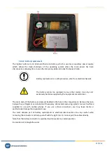
Page 218: ...tment you will need to use a screwdriver of the type PZ1 Pozidriv For the handling of the cables inside the compartment it is recommended to use a small flat screwdriver The first step to access the c...

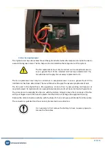
Page 219: ...s supplied by the equipment manufacturer The main body of the battery is simply embedded in the hole in the compartment Remove the main body with your fingers or use a help tool if necessary We recomm...

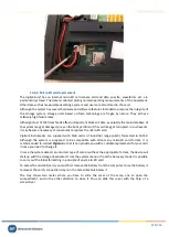
Page 220: ...led unit has been determined The manufacturer will supply the necessary replacement unit The fan used in the Vigilant has a life expectancy of more than 5 years working continuously at maximum power I...

Page 221: ...onvenient to replace the micro SD card Vigilant instruments are supplied with 4GB cards of industrial range pSLC formatted in FAT32 Although the system is supposed to be compatible with almost any mic...

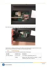
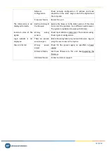
Page 222: ...ired Do not try to do it if you are not sure of the steps to follow and to have the right material 14 7 Troubleshooting The following table shows solutions for possible trouble with this device Sympto...

Page 223: ...different web browser The system is optimized to work with Chrome Incorrect value of the signals Wrong wiring sensors Check input LEDs see Indicators Check sensor wiring Check Vigilant configuration...

Page 224: ...y initiates its shutdown After it is down if power supply comes back the unit will start up again In case the power supply comes back during the shutting down the process will continue until it is dow...

Page 225: ...of the firmware This process can take several minutes so the unit must not be reset or turned off It is strongly recommended to delete the cache of the web navigator after system upgrade Some navigat...

Page 226: ...lowing instructions we will make a 440 Hz sine tone using the free audio editing software Audacity Adjust default sample rate and sample format Edit Preferences Quality Set the default sample rate to...

Page 227: ...FFT data transformation DM Demodulation X Technique for detecting HF bearing failures OB Orbits SCL widgets X Enables Shaft Centerline and Orbit widgets AC Advanced Capture X Allow advanced event base...

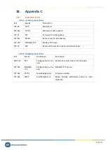
Page 228: ...data backup TCP 502 MODBUS TCP Modbus TCP slave TCP 22 SSH Reserved for remote support and maintenance 18 1 2 Outgoing connections Port Service Destination Description UDP 123 NTP Configurable by the...

Page 229: ...previous widget in cycle tab Focus next widget in cycle Layout Editor escape Exit layout editor r Move the desktop tab to the right shift r Move the desktop tab to the left Forms arrowdown Move form s...

Page 230: ...ht Move all cursors one sample right shift f Move all cursors 1 10 sample left shift g Move all cursors 1 10 sample right t x Open or close timeline Exit cursor mode w Show waveform z Reset zoom Wavef...

Page 231: ...ocus to previous source in cycle shift arrowleft Move all cursors one sample left shift arrowright Move all cursors one sample right Z Reset zoom Orbit arrowleft Move active cursor one sample left arr...

Page 232: ...ode in cycle S Show spectrum T Open or close timeline Shaft Centerline arrowleft Move active cursor one sample left arrowright Move active cursor one sample right x Exit cursor mode z Reset zoom Holdi...

Reviews: