Section 05 FUEL SYSTEM
Subsection 01 (FUEL TANK AND FUEL PUMP)
F18F0WA
2
1
TYPICAL
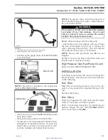
1. Disconnect hose from black and white valve
2. Hose pincher on vent hose (blue valve)
– Connect pump gauge tester (P/N 529 021 800)
to air inlet hose.
529 021 800
NOTE:
This pump is included in the engine leak
test kit (P/N 295 500 352).
295 500 352
– Install a hose pincher (P/N 295 000 076) on vent
hose (blue valve).
– Pressurize fuel system to 34 kPa (5 PSI).
– If pressure is not maintained locate leak and re-
pair/replace component leaking. To ease leak
search spray a solution of soapy water on com-
ponents, bubbles will indicate leak location.
NOTE:
The system must maintain a pressure of
34 kPa (5 PSI) during 10 minutes. Never pressur-
ize over 34 kPa (5 PSI).
WARNING
If any leak is found, do not start the engine
and wipe off any fuel leakage. Do not use
electric powered tools on watercraft unless
system has passed pressure test.
Before removing hose pincher and pump:
– Alternately touch and release with your finger
the blue valve nipple to feel if air is coming out
when removing hose pincher. This will indicate
that pressure relief valve is not blocked.
NOTE:
Ensure that grommets
no. 20
are not
plugged.
Reinstall hose to the black and white valve and
ensure valve is attached to body.
High Pressure Test (Fuel Pump Circuit)
Refer to FUEL PUMP PRESSURE TEST.
INSTALLATION
Assembly is essentially the reverse of disassem-
bly procedures. However pay particular attention
to the following.
Fuel Filter
New filter can be pressed back on by hand. En-
sure it is fully seated for complete filtering of the
fuel.
Reinstall fuel pump.
Fuel Pump
Align tab of gasket with tank neck and then align
arrow of fuel pump with tab of gasket.
Refer to following illustration for tightening se-
quence. Torque 1 to 4 at 1 N•m (9 lbf•
in
) and then
5 to 13 at 2 N•m (18 lbf•
in
).
smr2005-014
139
www.SeaDooManuals.net


