background image

Section 03 ENGINE SYSTEM

Subsection 03 (COOLING SYSTEM)

1

F18E26A

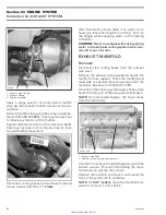
1. This becomes hot when thermostat opens

Last, refill expansion tank and install pressure cap.

When engine has completely cooled down,
recheck coolant level in radiator and coolant tank
and top up if necessary.

Test the density of the coolant using an antifreeze
hydrometer.

NOTE:

Follow hydrometer manufacturer instruc-

tions for proper use.

The reading should be some degrees below the
coldest temperature you expect in the area where
the watercraft is to be used. Add demineralized
water or antifreeze accordingly. Refill to the prop-
er level.

CAUTION:

Pure antifreeze will freeze at a

higher temperature than the optimal water/
antifreeze mix.

Using water tap instead of

demineralized

water,

would

contribute to

make deposits in cooling system and to reduce
antifreeze efficiency. This could lead to engine
overheating.

CARE

The coolant should be replaced annually or every
100 hours of use. Coolant should be replaced pri-
or to storage.

When servicing the hull, rotate watercraft either
way (seen from the rear) maximum to 90°.

F18L13A

TECHNICAL SPECIFICATIONS

TYPE

Closed loop cooling
system.

COOLANT FLOW

Flow from coolant pump.

TEMPERATURE
CONTROL

Thermostat.

SYSTEM BLEEDING

Self-bleed type through
expansion tank (hose at
uppermost point of circuit).

MONITORING
BEEPER

Turns on at 100°C (212°F).

COOLANT LIFE
CYCLE

100 hours or 1 year. Should
be replaced before storage.

42

smr2005-008

www.SeaDooManuals.net

Summary of Contents for 145A

Page 1: ...C M Y CM MY CY CMY K www SeaDooManuals net ...

Page 2: ...2005 Vehicle Shop Manual 4 TEC Series www SeaDooManuals net ...

Page 3: ...l Products Inc BRP or its affiliates Trademark of Bombardier Inc used under license SEA DOO BOMBARDIER ROTAX BOMBARDIER LUBE Sea Doo Learning KeyTM DESSTM Rotax O P A S TM TOPSTM This document contains the trademarks of the following companies Knight s Spray Nine is a trademark of Korkay System Ltd GTX is a trademark of Castrol Ltd Used under license Loctite is a trademark of Loctite Corporation S...

Page 4: ...RCRAFT CLEANING 9 ANTICORROSION TREATMENT 9 CHECKLIST 10 04 SPECIAL PROCEDURES 11 TOWING THE WATERCRAFT IN WATER 11 SUBMERGED WATERCRAFT 12 WATER FLOODED ENGINE 12 02 TROUBLESHOOTING 01 TROUBLESHOOTING CHART 15 ENGINE WILL NOT START 15 ENGINE HARD TO START 17 ENGINE STARTS BUT RUNS ONLY AT IDLE SPEED 18 ENGINE MISFIRES RUNS IRREGULARLY 18 ENGINE CONTINUALLY BACKFIRES 19 ENGINE DETONATION OR PINGIN...

Page 5: ...ICATIONS 47 04 EXHAUST SYSTEM 49 EXHAUST PIPE 51 EXHAUST MANIFOLD 54 MUFFLER 55 RESONATOR 56 EXHAUST OUTLET 56 05 REMOVAL AND INSTALLATION 59 ENGINE REMOVAL 59 CLEANING 63 INSTALLATION 63 04 ENGINE MANAGEMENT 1503 4 TEC 01 OVERVIEW 67 OPERATING PRINCIPLE 68 AIR INDUCTION 68 FUEL SYSTEM 70 ELECTRICAL SYSTEM 70 ENGINE MANAGEMENT SYSTEM EMS 72 EMS ENGINE MANAGEMENT SYSTEM FUNCTIONS 74 02 DIAGNOSTIC P...

Page 6: ...PS 128 TOPS VALVE 128 OIL SEPARATOR PRESSURE SENSOR OSPS 129 TOPS SWITCH 130 05 FUEL SYSTEM 01 FUEL TANK AND FUEL PUMP 133 GENERAL 135 REMOVAL 136 INSPECTION 137 INSTALLATION 139 TESTING PROCEDURES 140 06 ELECTRICAL SYSTEM 01 IGNITION SYSTEM 145 GENERAL 147 QUICK TEST WITH B U D S 147 VOLTAGE TEST 147 IGNITION COIL 148 SPARK PLUGS 149 IGNITION TIMING 149 02 CHARGING SYSTEM 151 GENERAL 153 TESTING ...

Page 7: ...EMOVAL 205 INSPECTION 208 INSTALLATION 209 LUBRICATION 213 03 REVERSE SYSTEM 215 DISASSEMBLY 217 INSPECTION 219 ASSEMBLY 219 ADJUSTMENT 219 04 VARIABLE TRIM SYSTEM 221 GENERAL 223 REMOVAL 223 DISASSEMBLY 223 INSPECTION 224 ASSEMBLY 224 INSTALLATION 224 ADJUSTMENT 225 08 STEERING SYSTEM 01 STEERING SYSTEM 227 DISASSEMBLY 229 ASSEMBLY 234 ALIGNMENT 236 02 OFF POWER ASSISTED STEERING SYSTEM O P A S 2...

Page 8: ...MENT 276 BUMPER REPLACEMENT 276 WAKE PYLON 276 SPONSON REPLACEMENT 278 SPONSON ADAPTOR 278 BAILER PICK UPS INSPECTION 278 DECALS REPLACEMENT 279 HULL AND BODY REPAIR 280 TOOLS AND MATERIALS LIST 282 10 TECHNICAL SPECIFICATIONS 01 GTX WAKE AND GTX SC MODELS 283 02 GTX LIMITED AND RXT MODELS 287 03 RXP MODELS 291 11 ELECTRICAL CONNECTORS AND WIRING DIAGRAMS 01 ELECTRICAL CONNECTORS 295 DEUTSCH CONNE...

Page 9: ...exact replicas of the parts The use of BRP parts is most strongly recommended when considering replacement of any component Dealer and or distributor assistance should be sought in case of doubt The engines and the corresponding components identified in this document should not be utilized on product s other than those mentioned in this document WARNING Unless otherwise specified engine should be ...

Page 10: ...g on watercraft Besides in the marine industry FRONT is called BOW and REAR is called STERN F01L45B 1 2 1 Left port 2 Right starboard The information and component system descrip tions contained in this manual are correct at time of writing BRP however maintains a policy of continuous improvement of its products without imposing upon itself any obligation to install them on products previously man...

Page 11: ...irated Engine ADC Analog to Digital Conversion AC Alternate Current APS Air Pressure Sensor ATS Air Temperature Sensor B U D S BRP Utility and Diagnostic Software CDI Capacitor Discharge Ignition CPS Crankshaft Position Sensor CSI Cooling System Indicator DC Direct Current DESS Digitally Encoded Security System DI Direct Injection E I N Engine Identification Number ECM Engine Control Module ECU El...

Page 12: ...he parts shown however they represent parts which have the same or a similar function CAUTION These watercraft are designed with parts dimensioned mostly in the metric sys tem However some components may be from the imperial system When replacing fasten ers make sure to use only those recommended by BRP As many of the procedures in this manual are inter related we suggest that before undertaking a...

Page 13: ...d positions TYPICAL PAGE F01A0CT Illustration number for publishing process Subsection title indicates beginning of the subsection Dotted box contains parts of a particular model or an exploded view Page number Italic sub title above exploded view indicate pertaining models Drop represents a liquid product to be applied to a surface In this case Loctite 243 to screw threads Bold face number indica...

Page 14: ...ther wise it must be timed Remove carburetors from intake manifold Disconnect fuel bypass line between carburetors twin carburetors Remove carburetor s from rotary valve cover DISASSEMBLY AND INSPECTION Using a suitable pump gauge tester perform the fol lowing test proceeding as follows Install pump gauge tester P N 295 000 083 on pulse nipple Pump tester until it reaches 28 kPa 4 PSI Diaphragm mu...

Page 15: ...r or allow emis sions levels to exceed their predetermined factory specifications EPA Emission Regulations All new 1999 and more recent Sea Doo water crafts manufactured by BRP are certified to the EPA as conforming to the requirements of the regulations for the control of air pollution from new watercraft engines This certification is con tingent on certain adjustments being set to factory standa...

Page 16: ...required Blind Holes A00A3MA 1 2 1 On threads 2 On threads and at the bottom of hole Clean threads bolt and hole with solvent Apply Loctite Primer N P N 293 800 041 on threads bolt and nut and allow to dry for 30 seconds Choose proper strength Loctite threadlocker Apply several drops along the threaded hole and at the bottom of the hole Apply several drops on bolt threads Tighten as required Stud ...

Page 17: ...e on bolt nut contact surfaces Adjusting Screw A00A3PA 1 2 1 Apply here 2 Plunger Adjust screw to proper setting Apply drops of proper strength Loctite thread locker on screw body contact surfaces Avoid touching metal with tip of flask NOTE if it is difficult to readjust heat screw with a soldering iron 232 C 450 F Stripped Thread Repair A00A3QA 5 8 6 7 1 2 3 4 1 Release agent 2 Stripped threads 3...

Page 18: ...d grinding Clean both mating surfaces with solvent Spray Loctite Primer N on both mating surfaces and on both sides of gasket Allow to dry 1 or 2 minutes Apply GASKET ELIMINATOR 518 P N 293 800 038 on both sides of gasket using a clean ap plicator Place gasket on mating surfaces and assemble immediately NOTE If the cover is bolted to blind holes above apply proper strength Loctite in the hole and ...

Page 19: ...Tighten fasteners to torque mentioned in explod ed views and or text When they are not specified refer to following table WARNING Torque wrench tightening specifications must strictly be adhered to Locking devices ex locking tabs elastic stop nuts self lock ing fasteners etc must be installed or replaced with new ones where specified If the efficiency of a locking device is impaired it must be ren...

Page 20: ...44 lbf in M5 3 3 5 N m 27 31 lbf in 4 5 5 5 N m 40 47 lbf in 7 8 5 N m 62 75 lbf in 8 10 N m 71 89 lbf in M6 6 5 8 5 N m 58 75 lbf in 8 12 N m 71 106 lbf in 10 5 15 N m 93 133 lbf in 16 N m 142 lbf in M8 15 N m 11 lbf ft 24 5 N m 18 lbf ft 31 5 N m 23 lbf ft 40 N m 30 lbf ft M10 29 N m 21 lbf ft 48 N m 35 lbf ft 61 N m 45 lbf ft 72 5 N m 53 lbf ft M12 52 N m 38 lbf ft 85 N m 63 lbf ft 105 N m 77 l...

Page 21: ... moment if so equipped I Supercharger drive gear shaft and lock washer if so equipped I 10 5 Emission related component 7 Replace for storage period or after 100 hours of use whichever comes first 10 Every 100 hours of use for supercharged engines Every 200 hours of use for supercharged intercooled engines COOLING SYSTEM Flushing exhaust system T 3 Hose and fasteners I I Coolant I R 7 Coolant expa...

Page 22: ...PULSION SYSTEM Drive shaft corrosion protection L 9 Drive shaft protection boot I 2 Drive shaft impeller splines normally aspirated and supercharged engines L Drive shaft impeller splines supercharged intercooled engines L Sacrificial anode I Shifter system cable I A L I A L VTS Variable Trim System if so equipped I A I A Impeller shaft seal sleeve and O ring I 6 Impeller and impeller wear ring cl...

Page 23: ...Fuel injection sensors verification Engine Management Inspection of check valves lines fasteners and pressurization 2 Filler neck fuel tank and fuel cap condition 2 Fuel tank straps Fuel Tank and Fuel Pump Refill fuel tank Refer to the appropriate OPERATOR S GUIDE ELECTRICAL SYSTEM Battery condition charging and installation Charging System Connection and routing of electric harness battery starte...

Page 24: ... Jet Pump and Drive System HULL and BODY Inspection of bailer pick ups Hull Body Ski wakeboard post and fasteners if so equipped Hull Body 1 Before installing new spark plugs it is suggested to burn the excess BOMBARDIER LUBE P N 293 600 016 or equivalent by starting the engine using the old spark plugs 2 Safety item covered in the annual safety inspection 3 If antifreeze was not changed for stora...

Page 25: ...ed prior to engine lubrication to ensure fuel sys tem components protection against varnish deposits Fill up fuel tank completely Ensure there is no water inside fuel tank CAUTION Should any water be trapped inside fuel tank severe internal damage will occur to the fuel injection system WARNING Fuel is inflammable and explosive under certain conditions Always work in a well ventilated area Do not ...

Page 26: ...e the water craft is out of the water the heat exchanger in the ride plate may become very hot Avoid any contact with ride plate as burns may oc cur NOTE The optional flushing connector adaptor P N 295 500 473 can be used with a quick con nect adapter to ease garden hose installation 1 F00E05A 2 1 Quick connect adapter 2 Flushing connector adapter F07E01C 3 2 1 TYPICAL 1 Flushing connector 2 Quick...

Page 27: ...cle Make sure coupler hose is properly locked to flushing connector Install a small hose pincher P N 295 000 076 sup plied inside vehicle tool kit on water outlet hose This prevent water from directly existing exhaust cooling system 295 000 076 This prevents water from directly exiting exhaust cooling system 1 2 F18E1UA 1 Coupler hose 2 Small hose pincher Attach other end of coupler hose to a gard...

Page 28: ...aust valves To fog the engine proceed as follows Remove the two bolts that hold the fuel rail on Remove the rail along with the three fuel injec tors Spray liberally BOMBARDIER LUBE lubricant P N 293 600 016 into the intake ports Crank engine several times while keeping throt tle fully depressed drown engine mode to dis tribute lubricant in cylinders on intake valves and exhaust valves Carefully i...

Page 29: ...ergent or with bilge cleaner Rinse thoroughly Lift front end of watercraft to completely drain bilge If any repairs are needed to body or to the hull touch up paint and Gelcote repair kit are available Re place damaged labels decals Wash the body with soap and water solution only use mild detergent Rinse thoroughly with fresh water Remove marine organisms from the hull Apply a nonabrasive wax CAUT...

Page 30: ...the cooling system in cool regions Lubricate the engine Lubricate throttle body Add antifreeze into intercooler and exhaust manifold where temperatures are below freezing Remove clean and store the battery Clean the bilge Wash the body Spray BOMBARDIER LUBE lubricant P N 293 600 016 over all metallic components in engine compartment and in throttle cable Apply the anticorrosion coating P N 219 700...

Page 31: ...se from the jet pump housing to the engine with a large hose pincher P N 529 032 500 529 032 500 This will prevent the exhaust cooling system from filling which may lead to water being injected in to and filling the exhaust system and the engine Without the engine running there isn t any exhaust pressure to carry the water out the exhaust outlet CAUTION Failure to do this may result in dam age to ...

Page 32: ...ination If necessary siphon and refill with fresh fuel To limit damages to the engine perform the fol lowing procedure as soon as possible Drain bilge if water is present If it was submerged in salt water spray bilge and all components with fresh water using a garden hose to stop the salt corroding effect CAUTION Never try to crank or start the en gine Water trapped in the intake manifold would en...

Page 33: ... 710 037 F18D2PA 1 F18D19A 1 Scavenge oil pump cover drain plug Connect the pump P N 529 035 880 to the fitting The front of the engine must be tilted down ap proximately 15 degrees to facilitate the removal of the oil Raise the rear of the boat according ly Siphon the oil from the fitting Level the engine Remove the pump and the fitting Apply Loctite 243 blue P N 293 800 060 and reinstall the dra...

Page 34: ...E SYSTEM section CAUTION Make sure that the ring seal carrier is not in contact with the PTO seal assembly neither with the carbon ring Connect a flush kit to the coolant line CAUTION Never run engine without supplying water to the exhaust cooling system when wa tercraft is out of water Run the engine for 5 minutes at 3000 RPM With the engine still running at 3000 RPM in stall a hose pincher to th...

Page 35: ...pump Check wiring then replace fuse Starting system fuse keeps on burning Check wiring starting system solenoid and MPEM Discharged or disconnected battery Check recharge Defective or disconnected start stop switch Check refer to STARTING SYSTEM Battery connections Check clean tighten Poor bad or corroded ground contacts engine starter etc Check clean repair Water fuel hydro lock Check refer to MA...

Page 36: ...m Check for fault codes Refer to DIAGNOSTIC PROCEDURES in ENGINE MANAGEMENT Engine drowned mode is active Release throttle lever Low battery voltage Recharge or replace battery Check fuel pump pressure output Check fuel pump fuse Low or no fuel pressure Check wiring harness Check fuel injector operation Replace as necessary Fuel injectors not working Check output signal from MPEM No spark at the s...

Page 37: ...valve Refer to ENGINE MANAGEMENT Wrong TPS zero setting Refer to ENGINE MANAGEMENT Throttle cable adjustment Refer to ENGINE MANAGEMENT Temperature too low for available battery capacity Battery capacity is not sufficient for cold temperature Air lock in fuel rail Refer to ENGINE MANAGEMENT Water in intake system defective MAP sensor Check and remove water Refer to SPECIAL PROCEDURES subsection Wa...

Page 38: ...TEM Weak spark Poor engine ground Check clean repair Low fuel pressure Check pump regulator injectors and hose pinchers or if filter is plugged Replace if necessary Stale or water fouled fuel Check siphon and refill Fuel filter dirty or restricted Check clean replace Clogged fuel injectors Remove and clean fuel injectors Lean fuel mixture Dry spark plug except when water fouled Defective sensor or...

Page 39: ...park Fouled defective spark plugs Clean replace Spark plugs Ignition coil wiring reversed Refer to WIRING DIAGRAM Incorrect setting Check reset refer to ELECTRICAL SYSTEM Ignition timing Defective trigger wheel CPS Check refer to ENGINE MANAGEMENT Engine Intake or exhaust valve s leak Pressure check engine refer to the 1503 4 TEC ENGINE SHOP MANUAL ENGINE DETONATION OR PINGING OTHER OBSERVATION PO...

Page 40: ...fuel pump pressure Incorrect throttle position sensor TPS adjustment Check and adjust TPS refer to ENGINE MANAGEMENT Improper timing chain alignment Refer to CYLINDER HEAD in the a1503 4 TEC ENGINE SHOP MANUAL Defective supercharger Check repair refer to the 1503 4 TEC ENGINE SHOP MANUAL Overheated engine See ENGINE OVERHEATS in this chart Engine revs lower than its maximum operational RPM Limp ho...

Page 41: ...oo low Check repair refer to CHARGING SYSTEM ENGINE RUNS TOO FAST VEHICLE CANNOT REACH ITS TOP SPEED OTHER OBSERVATION POSSIBLE CAUSE REMEDY Faulty rev limiter Check refer to ENGINE MANAGEMENT Improper impeller pitch too low Check replace refer to PROPULSION SYSTEM Engine RPM too high Damaged impeller Replace impeller Refer to PROPULSION SYSTEM Damaged leading or trailing edge of impeller Check re...

Page 42: ...sounds continuously Thermostat defective Check replace ENGINE SMOKE IN THE EXHAUST OTHER OBSERVATION POSSIBLE CAUSE REMEDY Coolant leak Check repair Refer to COOLING SYSTEM Intercooler leak if so equipped Check repair Refer to the 1503 4 TEC ENGINE SHOP MANUAL Damaged cylinder head gasket Check replace cylinder head gasket Water ingestion Inspect intake manifold for water infiltration White smoke ...

Page 43: ...tary seal on coolant pump shaft leaking Replace both seals Refer to PTO HOUSING in the appropriate ENGINE SHOP MANUAL Change oil Cylinder head gasket leaking Replace gasket Refer to the 1503 4 TEC ENGINE SHOP MANUAL Change oil Loose screws on cylinder head PTO housing or oil separator Retorque Change oil Oil contamination due to metal or plastic particles Replace possibly damaged parts Change oil ...

Page 44: ... supercharger if so equipped Check repair refer to the 1503 4 TEC ENGINE SHOP MANUAL Missing defective air intake hose Check replace air intake hose or clamps refer to AIR INTAKE SYSTEM INAPPROPRIATE SPEEDOMETER READING OTHER OBSERVATION POSSIBLE CAUSE REMEDY Faulty speed sensor or related circuits Refer to INSTRUMENTS AND ACCESSORIES MPEM was replaced and speedometer calibration data were not tra...

Page 45: ...OTE Prior to replacing an ECM or MPEM refer to the appropriate ECM MPEM section or ECM MPEM replacement in the ENGINE MANAGEMENT section and read carefully the tests to do before replacing an ECM MPEM that could otherwise be good smr2005 006 25 www SeaDooManuals net ...

Page 46: ...Section 03 ENGINE SYSTEM Subsection 01 AIR INTAKE SYSTEM AIR INTAKE SYSTEM SERVICE TOOLS Description Part Number Page hook tool 529 035 989 30 smr2005 029 27 www SeaDooManuals net ...

Page 47: ...Section 03 ENGINE SYSTEM Subsection 01 AIR INTAKE SYSTEM 4 TEC Naturally Aspirated Engine F18D30S 5 4 2 2 1 28 smr2005 029 www SeaDooManuals net ...

Page 48: ...Section 03 ENGINE SYSTEM Subsection 01 AIR INTAKE SYSTEM 4 TEC Supercharged and Supercharged Intercooled Engines F18D31S 5 1 2 2 3 4 smr2005 029 29 www SeaDooManuals net ...

Page 49: ...rt REMOVAL From storage compartment remove disconnect hose no 4 F18D32A front access door if so equipped smr2005 029 007_a 1 Access door front vent tube RXP only F18D33A rectifier voltage regulator wiring harness from air silencer F18D34A fuel tank straps refer to FUEL SYSTEM using hook tool P N 529 035 989 529 035 989 Pull air silencer out 4 TEC Supercharged and Supercharged Intercooled Engines F...

Page 50: ... tank out vent tube support 2 1 F18L1GA 2 3 1 Vent tube support 2 Remove retaining screws 3 Pay attention to nuts underneath tube from air intake hose Pull tube out R1503motr224C INSTALLATION Reverse removal operation order and pay atten tion to the following Ensure that tubes are well secured with hoses and there is a tight fit smr2005 029 31 www SeaDooManuals net ...

Page 51: ...placed at the same time Oil change and oil filter replacement should be done with a warm engine WARNING The engine oil can be very hot Wait until en gine oil is warm Dispose oil and filter as per your local environmen tal regulations OIL LEVEL VERIFICATION CAUTION Check level frequently and refill if necessary Do not overfill it would make the engine smoke and reduce its power Operating the engine...

Page 52: ...TION Never run engine longer than 5 min utes Drive line seal has no cooling when wa tercraft is out of water Reinstall dipstick push in completely Remove dipstick and read oil level It should be between marks F18D2MA 1 2 3 1 Full 2 Add 3 Operating range Otherwise add oil until its level is between marks as required To add oil unscrew oil cap Place a funnel into the opening and add the recommended ...

Page 53: ...ress throttle lever and HOLD then crank engine Crank engine for 10 seconds Siphon oil again Repeat the crank siphon cycle 2 3 times Oil Filling Refill engine with oil meeting the specific require ments of the engine Refer to TECHNICAL SPEC IFICATIONS Reinstall oil filler cap and dipstick OIL TYPE AND SYSTEM CAPACITY Refer to TECHNICAL SPECIFICATIONS For refill ing procedure refer to OIL LEVEL VERI...

Page 54: ...PICAL 1 Inlet bore from the oil pump to the oil filter 2 Outlet bore to the engine oil providing system Installation For installation reverse the removal procedure Pay attention to the following details Install a new oil filter Install O ring on oil filter cover R1503motr116A TYPICAL Torque oil filter screw to 9 N m 80 lbf in 36 smr2005 007 en www SeaDooManuals net ...

Page 55: ... SYSTEM SERVICE TOOLS Description Part Number Page pliers Oetiker 1099 295 000 070 46 test cap 529 035 991 39 vacuum pressure pump 529 021 800 39 SERVICE PRODUCTS Description Part Number Page premixed antifreeze 219 700 362 40 smr2005 008 37 www SeaDooManuals net ...

Page 56: ...housing including thermostat opens at 87 C 188 F and coolant pump impeller Bleed hose from cylinder head to expansion coolant tank Expansion coolant tank Coolant temperature sensor CTS activates when temperature exceeds 100 C 212 F Coolant flows to oil cooler Oil cooler Coolant returns from oil cooler Coolant returns from ride plate 38 smr2005 008 www SeaDooManuals net ...

Page 57: ...he thermostat directly back to the coolant pump impeller or it takes its way through the ride plate which operates as a heat exchanger Engine coolant is also directed towards the oil cooler coolant type Coolant temperature sensor and bleed nipple are located on the cylinder head 1 F18E0XA 2 1 Bleed nipple 2 Coolant temperature sensor CTS CAUTION Never modify cooling system ar rangement otherwise s...

Page 58: ... in cold areas always replenish the system with 50 antifreeze and 50 dem ineralized water Pure antifreeze will freeze at a higher temperature than the optimal water antifreeze mix Always use ethylene glycol an tifreeze containing corrosion inhibitors specif ically recommended for aluminum engines Using water tap instead of demineralized water would contribute to make deposits in cooling system and...

Page 59: ...system as described below Refilling the System Watercraft should be level engine cold and drain plug removed for refilling Place a container under drain plug to collect an tifreeze Ask someone to pour antifreeze in expansion tank while watching antifreeze and air bubble flowing out through drain hole When no air bubbles escape reinstall drain plug Torque to 8 3 N m 73 lbf in 1 F18E1LA 1 Pour antif...

Page 60: ...e will freeze at a higher temperature than the optimal water antifreeze mix Using water tap instead of demineralized water would contribute to make deposits in cooling system and to reduce antifreeze efficiency This could lead to engine overheating CARE The coolant should be replaced annually or every 100 hours of use Coolant should be replaced pri or to storage When servicing the hull rotate wate...

Page 61: ...ion 03 ENGINE SYSTEM Subsection 03 COOLING SYSTEM OPENED LOOP COOLING SYSTEM exhaust system GTX 4 TEC and WAKE smr2005 008 001_a GTX 4 TEC Supercharged smr2005 008 002_a smr2005 008 43 www SeaDooManuals net ...

Page 62: ...Section 03 ENGINE SYSTEM Subsection 03 COOLING SYSTEM GTX 4 TEC Limited and RXT smr2005 008 003_a RXP smr2005 008 004_a 44 smr2005 008 www SeaDooManuals net ...

Page 63: ...ont of manifold for the models without intercooler smr2005 008 005_a TYPICAL MODELS WITH INTERCOOLER 1 Intercooler 2 Water inlet 3 Toward exhaust manifold 4 Exhaust manifold 5 Water inlet from intercooler 6 Water outlet 2 3 F18E1FA 1 TYPICAL MODELS WITHOUT INTERCOOLER 1 Exhaust manifold 2 Water inlet 3 Water outlet Water enters the manifold end and is directed to water jackets of exhaust manifold ...

Page 64: ... is expulsed from mufflers then through the exhaust outlet in transom area Intercooler Supercharged Intercooled Engine For the intercooler servicing refer to the 1503 4 TEC ENGINE SHOP MANUAL Clamp Replacement To cut or secure Oetiker clamps of cooling system hoses use the pliers Oetiker 1099 P N 295 000 070 1 F01B2KA 2 1 Cutting clamp 2 Securing clamp CARE For flushing and winterization procedure...

Page 65: ...OW Flow from jet pump no water pump TEMPERATURE CONTROL Calibrated outlet fittings no thermostat SYSTEM BLEEDING Self bleed type hose at uppermost point of circuit SYSTEM DRAINING Self drain type hose at lowest point of circuit SYSTEM FLUSHING Flushing connector adapter on jet pump support smr2005 008 47 www SeaDooManuals net ...

Page 66: ...on Part Number Page exhaust outlet tool 295 000 132 56 spring installer remover 529 035 989 51 SERVICE PRODUCTS Description Part Number Page high temperature RTV sealant 293 800 090 52 Loctite 518 293 800 038 55 Loctite silicone sealant clear 293 800 086 57 smr2005 009 49 www SeaDooManuals net ...

Page 67: ...bf in 6 1 5 3 2 2 7 N m 62 lbf in 8 9 11 10 12 14 13 Body High temperature RTV sealant 4 N m 35 lbf in Loctite 518 4 10 4 N m 35 lbf in 12 14 Silicone sealant 13 23 N m 17 lbf ft Body 11 N m 97 lbf in Silicone sealant RXP models smr2005 009 001_aen 50 smr2005 009 www SeaDooManuals net ...

Page 68: ...18L2GA 2 1 Seat support 2 Remove screws RXP Models Remove seat Remove engine cover Refer to HULL AND BODY All Models Disconnect the 3 cooling hoses from exhaust pipe no 1 2 3 F18D0IA 1 1 Exhaust pipe 2 Gear clamp 3 Exhaust clamp Loosen the clamps no 2 to the top portion of the muffler hose no 3 between muffler no 4 and the exhaust pipe no 1 1 F18D0RA 2 1 Muffler hose clamp 2 Exhaust pipe Detach th...

Page 69: ...y particular atten tion to the following Apply high temperature RTV sealant P N 293 800 090 on the welds of the exhaust pipe straight end while the exhaust pipe is removed from the muf fler 1 F18D0TA 2 1 High temperature RTV sealant 2 Exhaust pipe straight end Loosely install clamps no 2 on muffler hose no 3 Insert the exhaust pipe straight end in the muffler hose Align the exhaust pipe flange to ...

Page 70: ...bor clamps must be separat ed by 4 5 mm 5 32 3 16 in and the screws must be at least 25 mm 1 in apart Tighten both upper clamps then torque the bottom clamp smr2005 009 002_a 1 Exhaust pipe step 2 Muffler hose 3 Muffler hose clamp 4 5 mm 5 32 3 16 in apart 4 Bottom clamp Finalize alignment by rotating axially and mov ing longitudinally the muffler so that the exhaust pipe flange makes perfect cont...

Page 71: ... connector CAUTION Never run engine without supplying water to the exhaust cooling system when wa tercraft is out of water EXHAUST MANIFOLD Removal Disconnect the cooling hoses from the exhaust pipe no 1 Remove the exhaust clamp no 6 and detach the muffler from its support Move the muffler no 4 rearwards to separate the exhaust pipe from the manifold See above in EXHAUST PIPE Disconnect the coolin...

Page 72: ...10 N m 89 lbf in as per follow ing illustrated sequence Repeat the procedure torquing screws again to 10 N m 89 lbf in R1503motr152A 7 5 1 3 9 11 8 6 4 2 10 12 After installation ensure there is no coolant or ex haust gas leak when the engine is running Test run the engine while supplying water to the flush ing connector CAUTION Never run engine without supplying water to the exhaust cooling syste...

Page 73: ...10 from exhaust outlet no 12 Install outlet hose on resonator Install resonator in position while inserting outlet hose no 10 on exhaust outlet After installation ensure there is no coolant or ex haust gas leak when the engine is running Test run the engine while supplying water to the flush ing connector CAUTION Never run engine without supplying water to the exhaust cooling system when wa tercra...

Page 74: ...ge Check hose Replace any de fective part Installation Installation is essentially the reverse of the re moval procedures However pay particular atten tion to the following Apply Loctite silicone sealant clear P N 293 800 086 on the gasket no 14 to seal the bilge Test the bilge for water leaks smr2005 009 57 www SeaDooManuals net ...

Page 75: ... 413 711 809 63 ENGINE REMOVAL Use the VCK Vehicle Communication Kit P N 529 035 981 and release the fuel pressure in the fuel system Refer to ENGINE MANAGEMENT sec tion 529 035 981 In order to remove engine from watercraft pro ceed as follows First disconnect battery cables from battery WARNING Always disconnect battery cables exactly in the specified order BLACK negative cable first then the RED...

Page 76: ...e engine cover Refer to HULL AND BODY Remove connectors from engine connector bracket then disconnect Refer to WIRING DIA GRAMS Disconnect ECM and remove from engine to pre vent any possible damage while pulling engine out 3 F18Z0JB 1 2 1 Remove connectors 2 Disconnect ECM 3 Remove ECM Unplug VTS connector Cut locking ties retaining vehicle wiring harness to engine 1 F19D06A VEHICLE WIRING HARNESS...

Page 77: ...ercharger and air duct On Intercooled models disconnect water hoses from intercooler 1 R1503motr356B 1 Disconnect hoses here RXP 4 TEC Models Throttle Cable Remove inlet hose from throttle body Disconnect throttle cable from throttle body R1503motr252A 2 1 1 Detach hose 2 Disconnect cable Disconnect fuel rail supply line Disconnect water inlet hose coming from jet pump connected to the intercooler...

Page 78: ... component removal CAUTION Take care not to damage cables 1 F18D11A 1 TYPICAL 1 Lifting brackets RXP 4 TEC Models Slightly move engine rearward to take advantage of the larger opening The engine have to be hooked up at an additional location See illustration 1 F19D08A 1 Hook up a steel rope chain here Carefully lift engine by the side with the steel rope chain and rotate engine so that it can be p...

Page 79: ...gine INSTALLATION CAUTION Whenever engine is removed from watercraft engine jet pump alignment must be performed at reinstallation Installation of engine in watercraft is essentially the reverse of removal procedures However pay particular attention to the following Rubber Mount Shim and Screw Check tightness and condition of rubber mounts If they have been removed apply Loctite 243 blue P N 293 8...

Page 80: ...e P N 529 035 507 529 035 507 529 035 506 Alignment shaft P N 295 000 141 295 000 141 Engine alignment adapter P N 529 035 719 529 035 719 To verify alignment proceed as follows Secure plate and support to hull with four nuts F19D0AA Install engine alignment adapter P N 529 035 719 in engine PTO housing 1 F18D18A 1 Engine alignment adapter Carefully slide shaft through support Insert shaft end int...

Page 81: ... mounts to correct alignment CAUTION Whenever shims are used to cor rect alignment never install more than 5 mm 0 196 in shim thickness 1 F18D15A TYPICAL 1 Shim Engine Support Screws Apply Loctite 243 blue P N 293 800 060 on screw threads Torque engine support screws to 25 N m 18 lbf ft when procedure is completed 1 1 1 Loctite 243 Loctite 243 Loctite 243 F18D10B 1 2 1 Loctite 243 2 1 Torque to 25...

Page 82: ...ust throttle cable then perform the TPS reset as specified in EN GINE MANAGEMENT Check hose condition and pressure test fuel sys tem refer to FUEL SYSTEM section WARNING Whenever doing any type of repair on wa tercraft or if any components of the fuel sys tem are disconnected a pressure test must be done before starting engine Verify all electrical connections Run engine and ensure there is no lea...

Page 83: ...Purpose Electronic Module KS Knock Sensor CPS Cranshaft Position Sensor OPS Oil Pressure Sensor OSPS Oil Separator Pressure Sensor CTS Coolant Temperature Sensor CAPS Camshaft Position Sensor EGTS Exhaust Gas Temperature Sensor MAPS Manifold Air Pressure Sensor MATS Manifold Air Temperature Sensor TOPS Tip Over Protection System Con A Connector for Engine Wiring Harness Con B Connector for MPEM Co...

Page 84: ...S 4 TEC Supercharged Engine Air for combustion is drawn at the back of the en gine by a mechanical driven supercharger The compressed air flows through the throttle body and is controlled by a throttle plate and an idle by pass valve The air continues through the intake manifold which contains the flame arrester and goes into the cylinder head 2 1 R1503motr267A 1 Supercharger 2 Throttle body 4 TEC...

Page 85: ...mperature sensor MATS 4 5 R1503motr268A 3 2 1 6 7 INTAKE MANIFOLD 4 TEC SUPERCHARGED 1 Engine Control Module ECM 2 Fuel rail 3 Injector 4 Throttle body 5 Ignition coil 6 Manifold air pressure sensor MAPS 7 Manifold air temperature sensor MATS 8 3 2 R1503motr333A 5 9 7 10 6 1 4 INTAKE MANIFOLD 4 TEC SUPERCHARGED INTERCOOLED 1 Engine Control Module ECM 2 Fuel rail 3 Injector 4 Throttle body 5 Igniti...

Page 86: ...cylinder head Fuel Pump Module The fuel pump module is located inside the fuel tank The module includes the fuel pump fuel pressure regulator and fuel level sensor R1503motr217A The fuel pump provides fuel pressure and flow rate to the system Fuel Pressure Regulator A fuel pressure regulator controls the pressure in the system and allows the excess of fuel to return to the fuel tank The fuel press...

Page 87: ...ECM and VCM Interaction with Electrical System COMPASS OUTSIDE AIR TEMPERATURE SENSOR COMMUNICATION LINK COMMUNICATION LINK POWER TO ECM INFORMATION CENTER SET AND MODE SWITCHES SPEED SENSOR FUEL LEVEL SENDER BEEPER DEPTH GAUGE START STOP SWITCH STARTING SOLENOID FUEL PUMP FUEL INJECTORS IGNITION COILS TOPS VALVE TOPS SWITCH CAPS INFORMATION CENTER ECM MPEM TPS MAPS MATS CTS EGTS KS OPS OSPS CPS D...

Page 88: ...ts power by the MPEM which is di rectly powered by the battery It is responsible for the following engine management electrical func tions interpreting information distributing information start stop function DESS Digitally Encoded Security System ignition timing control injection control engine RPM limiter etc The ECM applies the proper map injection and ig nition for optimum engine operation in ...

Page 89: ...ccess to most functions of the informa tion center gauge without starting the engine Gauges are supplied with current whenever the safety lanyard cap is installed on its post Fuel Pump Current Supply The fuel pump will be activated for 2 seconds to build up pressure in the fuel injection system on ly when connecting the safety lanyard cap to the post Addition of Electrical Accessories Every time a...

Page 90: ...tr220T 1503 4 TEC CONTROL SYSTEM INPUTS OUTPUTS Idle bypass valve Fuel injector Ignition coil 3 TOPS valve Starter solenoid Fuel pump Communication port to VCM Tip over protection system TOPS Start Stop switch Digitally Encoded Security System DESS Battery voltage BV Knock sensor KS Throttle position TPS Crankshaft position CPS Coolant temperature CTS Manifold air temperature MATS Manifold air pre...

Page 91: ... knock sensor detects it and the ECM retards the ignition advance temporarily it goes in a specific mode until detonation stops The ECM is able to evalu ate the knocking cylinder and modifies the ignition advance just on the detonating one Ignition Coils Three separate ignition coils induce voltage to a high level in the secondary windings to produce a spark at the spark plug The ignition coils re...

Page 92: ... safety lanyard is not left on its post after engine is stopped IMPORTANT Leaving the safety lanyard on its post when engine is not running will slowly dis charge the battery Engine Modes of Operation The ECM controls different operation modes of the engine to allow proper operation for all possi ble conditions Cranking start up idle warm up part load full load Sea Doo Learning Key lim ited vehicl...

Page 93: ...onitoring System The ECM monitors the electronic components of the fuel injection system and also the engine components of the electrical system The MPEM monitors the vehicle electrical system and the accessories When a fault occurs it sends visual messages through the information center and or audible signals through a beeper to inform you of a particular condition Refer to the DIAGNOSTIC PROCEDU...

Page 94: ...odes to diagnose the trouble NOTE Fault codes the letter P followed by 4 digits P 1234 can be displayed in the informa tion center for troubleshooting With safety lan yard on its post press 5 times the SET button to start the display of P codes onboard diagnostic Press MODE to scroll codes if more than one is present When the list is over END will appear When END appears press MODE to exit F18L09D...

Page 95: ...ank CTS Coolant Temperature Sensor WTS Water Temperature Sensor ECM ECU Module EGTS Exhaust Gas Temperature sensor ETS Exhaust Temperature Sensor Idle bypass valve DLA Digital Linear Actuator Idle actuator Idle valve Information center Cluster MAPS Manifold Air Pressure Sensor APS Air Pressure Sensor or Atmospheric Pressure Sensor MATS Manifold Air Temperature Sensor ATS Air Temperature Sensor or ...

Page 96: ... does not work check safety lanyard condition with B U D S Replace safety lanyard if reported defective Defective safety lanyard Use another programmed safety lanyard Dried salt water or dirt in safety lanyard cap Clean safety lanyard cap to remove salt water Defective DESS post Refer to ENGINE MANAGEMENT section 1 long beep while installing safety lanyard on post Improper operation of ECM or defe...

Page 97: ... beep every 1 minute interval Bilge pump circuit low or high voltage if so equipped Refer to ENGINE MANAGEMENT section Low fuel level Refer to INSTRUMENTS AND ACCESSORIES section A 2 seconds beep every 5 minutes interval Fuel tank level sensor or circuit malfunction Refer to INSTRUMENTS AND ACCESSORIES section High engine coolant temperature Refer to COOLING SYSTEM Continuously beeps High exhaust ...

Page 98: ...ir If bad wiring repair Inspect wiring and sensor resistance test If bad TPS replace and reset Closed Throttle and Idle Actuator Test sensor operation wear test Replace and reset Closed Throttle and Idle Actuator TPS ADAPTATION FAILURE Fault It is caused by the idle position moving out of an acceptable range Following failures can be effected by a TPS Adaptation Failure Idle speed is out of range ...

Page 99: ...genuine particularly in the ignition system Installing resistive caps non resistive spark plugs or im proper knock sensor wiring routing may lead to generate this fault code Electrical noise might also lead engine to oc casional cutout without generating a fault code when engine is restarted When looking at the fault code pay attention to the count value in the software B U D S A value between 1 a...

Page 100: ...heck system circuits A 12 A 28 and A 40 Make sure that the sensor housing is correctly inserted into the manifold Check sensor connector for a 5 volts on pin 1 b 0 volt on pin 2 c 0 volt on pin 3 Manifold atmospheric pressure sensor shorted to ground 15 Flash CHK ENG N Y N Fault is recovered P0107 Manifold barometric pressure sensor shorted to ground 15 Flash CHK ENG Y N N Fault is recovered Possi...

Page 101: ...lash CHK ENG N Y N Fault is recovered Possible cause Damaged sensor damaged circuit wires damaged connector or damaged ECM pins Service action Check the sensor for approximately 2280 to 2736 ohms at 19 to 21 C 66 to 70 F Check for approximately 2280 to 2736 ohms at 19 to 21 C 66 to 70 F between ECM connector pins 7 and 21 P0112 Intake manifold temperature sensor shorted to ground 15 Flash CHK ENG ...

Page 102: ...0117 Engine temperature sensor short circuit to ground 5 Flash CHK ENG N Y N Fault is recovered Possible cause Damaged sensor damaged circuit wires damaged connector or damaged ECM pins Service action Check for debris or blockage in cooling system Check the sensor for approximately 2280 to 2736 ohms at 19 to 21 C 66 to 70 F Check for approximately 2280 to 2736 ohms at 19 to 21 C 66 to 70 F between...

Page 103: ...ing throttle Check physical stops for wear P0123 Throttle position sensor out of range short circuit to 12 V or open circuit 15 Flash CHK ENG N Y N Key is removed Possible cause Damaged sensor damaged circuit wires damaged connector or damaged ECM pins Damaged or out of alignment throttle bodies or sensor Service action Check for 0 volt on sensor connector pin 1 Check for 5 volts on sensor connect...

Page 104: ...4 to 12 6 ohms between engine connector pin 1 and ECM connector pin 15 Check for 12 volts on pin 2 of injector connector P0262 Inj 1 short circuit to 12 V 15 Flash CHK ENG N Y N Fault is recovered Possible cause Damaged injector damaged circuit wires damaged connector or damaged ECM output pins Service action Check for 11 4 to 12 6 ohms between engine connector pin 1 and ECM connector pin 15 Check...

Page 105: ...se Damaged sensor damaged circuit wires damaged connector or damaged ECM output pins Service action Bring engine to 5000 RPM If fault code appears then check for approximately 5 Mohms between system circuits A 9 and A 23 P0336 Crank position sensor wrong engine RPM detected 15 Flash CHK ENG Possible cause Damaged sensor damaged circuit wires damaged connector damaged ECM pins or damaged tooth whee...

Page 106: ...e CAPS check for 12 volts on sensor connector pin 3 Check continuity for circuits A 20 A 34 and terminal 4 on engine connector P0351 Ignition coil 1 open circuit or shorted to ground or to 12 V 15 Flash CHK ENG N Y 5000 Engine is stopped Possible cause Damaged coil damaged circuit wires damaged connector or damaged ECM output pins Service action Check for 0 85 to 1 15 ohms between engine connector...

Page 107: ... circuit 4 Flash SENSOR Y Y N Fault is recovered Possible cause Damaged sensor damaged circuit wires damaged connector or damaged MPEM output pins Service action Check voltage between system circuit 1 21 and battery ground DLA output stage cutoff memory difference 15 Off CHK ENG DLA output stage fault 15 Off N A Y N N Fault is recovered DLA open circuit 15 Off N A Y N N Fault is recovered P0505 DL...

Page 108: ...system circuits A 10 and A 26 P0545 Exhaust gas temperature sensor shorted to ground 5 Flash CHK ENG Y N Y N Fault is recovered Possible cause Damaged sensor damaged circuit wires damaged connector or damaged ECM output pins Service action Check for approximately 2280 to 2736 ohms at temperature of 19 to 21 C 66 to 70 F between system circuits A 10 and A 26 Exhaust gas temperature sensor shorted t...

Page 109: ...res damaged connector damaged ECM output pins Diagnostic connector cap not connected Service action Check system circuits 1 16 1 17 1 10 1 11 2 10 2 11 Connect diagnostic connector cap P0600 CAN communication problem MPEM message missing 15 Flash N A Y Y N Fault is recovered Possible cause Damaged circuit wires damaged connector or damaged ECM output pins Service action Check system circuits 2 10 ...

Page 110: ...lt P0604 symptom 136 P0605 EEPROM faulty 15 Flash CHK ENG Possible cause Damaged ECM Service action No service action available for fault P0605 symptom 137 P0605 Checksum fault EEPROM 15 Flash CHK ENG Possible cause Damaged ECM Service action No service action available for fault P0605 symptom 143 P0605 Coding ID checksum fault 15 Flash CHK ENG Possible cause Damaged ECM Service action No service ...

Page 111: ...ailure Starter relay shorted to ground 5 Flash CHK ENG N fault detected while cranking Y N Fault is recovered P0616 Starter relay open circuit 5 Flash CHK ENG Y Y N Key is removed Possible cause Damaged solenoid damaged circuit wires damaged connector or damaged ECM output pins Service action Verify 10 A fuse Check for 12 volts on pin 2 of the starter relay P0617 Starter relay shorted to 12 V 5 Fl...

Page 112: ... TPS Check battery voltage Replace TPS Replace idle bypass valve P1200 Blow by valve shorted to ground or open circuit 5 Flash CHK ENG Y N Y 5000 Fault is recovered Possible cause Blow by valve failure damaged circuit wires damaged connector damaged ECM pins or ECM failure Service action Check for 1 27 to 2 47 ohms on component P1201 Blow by valve shorted to 12 V 5 Flash CHK ENG N N N N A Possible...

Page 113: ...tion Check for no continuity between system circuit 2 13 and battery ground Connect or disable lake water temperature sensor in setting page P1511 Lake temperature sensor circuit high voltage 15 Off SENSOR Y Y N N A Possible cause Damaged sensor damaged circuit wires damaged connector or damaged MPEM output pins Service action Check for 6528 3 to 25403 3 ohms between system circuits 2 13 and 2 4 C...

Page 114: ... 167 5 ohms between system circuits 2 8 and 2 9 Connect or disable VTS in setting page P1591 VTS Position Sensor Circuit Low Voltage 15 Off SENSOR N Possible cause Damaged sensor damaged circuit wires damaged connector or damaged MPEM output pins Service action Check for 24 to 167 5 ohms between system circuits 2 8 and 2 9 Connect or disable VTS in setting page P1592 VTS Position Sensor Circuit Hi...

Page 115: ...Remove DESS key and check for an open circuit on system circuit B 38 P1656 DESS line shorted to ground 15 Flash CHK ENG Y N N N A Possible cause Damaged safety switch damaged circuit wires damaged connector or damaged ECM output pins Service action Remove DESS key and check for an open circuit on system circuit B 38 P1660 Bilge pump shorted to ground or open circuit 5 N A N A Y N N N A Possible ca...

Page 116: ...Y Y N N A Possible cause Damaged component damaged circuit wires damaged connector or damaged MPEM output pins Service action Connect component or disable spare output 2 in setting page P1679 Spare output 2 shorted to 12 V 15 N A N A Y Y N N A Possible cause Damaged component damaged circuit wires damaged connector or damaged MPEM output pins Service action Connect component or disable spare outpu...

Page 117: ... Possible cause Damaged VTS damaged circuit wires damaged connector or damaged MPEM output pins Service action Check for 12 volts between system circuits 2 7 and 2 1 when VTS UP is activated P1691 VTS control up circuit shorted to battery 15 Off N A Y Y N N A Possible cause Damaged VTS damaged circuit wires damaged connector or damaged MPEM output pins Service action Check for 12 volts between sys...

Page 118: ...tion Always OFF 2 second beep every 15 minutes 2 second beep every 58 seconds 2 second beep every 5 minutes Always ON continuously beep BEEPER PATTERN BEEPER CODE 5 4 2 NOTE 6 15 2 SEC 15 MIN 58 SEC ON OFF 2 SEC 2 SEC 5 MIN ON OFF ON OFF ON OFF ON OFF F18R0GS smr2005 012 103 www SeaDooManuals net ...

Page 119: ...eper diagnostic connector 3 P0616 Y Spare fuse 5 P1678 Y Electric starter fuel pump 10 P0231 Y MPEM 2 P0600 N VTS if so equipped 7 5 P1690 P1692 N EMS start stop circuit 5 None N 10A 2A 10A 1A 10A 10A 3A 5A 10A 2A 7 5A 5A 10A 2A 10A 1A 10A 10A 3A 5A 10A 2A 7 5A 5A 10A 2A 10A 1A 10A 10A 3A 5A 10A 2A 7 5A 5A Depth gauge if so equipped or spare fuse TOPS Cylinder 3 ignition coil and injection Informa...

Page 120: ...e actuator For more information pertaining to the use of the software B U D S use its help which contains de tailed information on its functions WARNING If the computer you are using is connected to the 110 Vac power outlet there is a poten tial risk of electrocution when working in con tact with water Be careful not to touch water while working with the VCK Electrical Connections F12H0DA 1 2 TYPI...

Page 121: ...ns on VCK and watercraft VCK Supply The VCK MPI box can use the watercraft power for its supply The safety lanyard must be connected in order to use the watercraft as a power source If watercraft power is used every time the safety lanyard is taken off the DESS post the kW2000 protocol will have to be re activated Changes in ECM Anytime a change is brought in ECM through B U D S there will be an E...

Page 122: ...to have an overview of problems and suggested solutions When replacing a component always check its operation after installation Whenever watercraft is out of water and engine is running ensure to supply water through the con nector on jet pump support to cool down exhaust system CAUTION Never run engine without supplying water to the exhaust cooling system when wa tercraft is out of water FUEL SY...

Page 123: ...onnections for damage and that NO fuel line is disconnect ed prior to installing the safety lanyard on the DESS post Always perform the high pressure test if any component has been removed A pressure test must be done be fore connecting the safety lanyard The fuel pump is started each time the safety lanyard is installed and it builds pressure very quick ly To check fuel rail for leaks first press...

Page 124: ...ly by unplugging and replugging the MPEM or ECM The voltage and current might be too weak to go through dirty wire terminals Check carefully if terminals show signs of moisture corrosion or if they look dull Clean terminals properly and then coat them prior to assembling as follows NOTE Do not apply dielectric grease or any other lubricant on the ECM or MPEM connectors Other connectors Apply a sil...

Page 125: ...r and heated with a heat gun while it is still connected to the harness to see if the ECM will detect the high temperature condition and generate a fault code NOTE In case of overheating EGTS and CTS do not generate fault codes A message will be dis played on the information center the beeper will be activated and the EMS will be set in limp home mode ECM Connectors The most recommended and safest...

Page 126: ... con trols the idle speed of the engine If desired the engine RPM can be measured fol lowing this procedure Use tachometer P N 529 014 500 529 014 500 Wrap the tachometer s wire a few times around the protruding part of ignition coil A32CCIA TYPICAL Start engine to verify engine RPM IGNITION TIMING The ECM is able to determine the exact position of camshaft and crankshaft That means that no igniti...

Page 127: ... per form the operations described in IF THE PREVI OUS MPEM WAS NOT READ with B U D S be low ECM Replacement CAUTION Never try to use a 4 TEC Super charged ECM on a naturally aspirated engine Doing so will automatically lead to a misfunc tion of the Engine Management System EMS and will cause irregular combustion which will damage the engine Always make sure to replace the ECM by an appropriate un...

Page 128: ...Manually activate the options installed on vehi cle under the Setting tab NOTE The MPEM serial number can be found on the MPEM sticker that also shows the P N NOTE If an option is installed but not checked in B U D S the information center will not display that option If an option is checked in B U D S but not installed in vehicle a fault code will be generated Continue procedure as per FINALIZING...

Page 129: ...st Check continuity of the circuits according to the wiring diagram in the ELECTRICAL CONNEC TORS AND WIRING DIAGRAMS section of this manual If wiring harness is good check the respective sensor actuator as described in this section Otherwise repair the connectors replace the wiring harness or the ECM MPEM as diagnosed Removal Remove fuel rail cover Disconnect the wiring harness from all sensors a...

Page 130: ...ring for the MATS with a locking tie to support the cables 1 R1503motr204A 1 Locking tie Install all remaining parts which has been re moved FUEL INJECTOR IMPORTANT Never mix up fuel injectors of naturally aspirated and supercharged 4 TEC en gines Doing so will automatically lead to a misfunction of the EMS and will cause a bad engine calibration Leakage Test To perform a leakage test the injector...

Page 131: ...ntinuity of cir cuit as per following table If it is good try a new MPEM CIRCUIT NUMBER AMP CONNECTOR NO 2 INJECTOR NUMBER 2 16 1 2 17 2 2 18 3 Resistance Test Reconnect the injector and disconnect the ECM connector A Remove safety lanyard and wait 15 seconds Dis connect engine connector CAUTION Before unplugging engine connec tor always remove safety lanyard and wait 15 seconds Otherwise damage t...

Page 132: ...l rail 1 2 R1503motr164A 3 FUEL RAIL ASS Y 1 Fuel injector 2 Injector clip 3 O ring Installation For the installation reverse the removal proce dure Paying attention to the following details If you reinstall a used injector carefully inspect O ring condition before reinstalling fuel injector Replace O ring with a new one if damaged In sert the fuel injector in place with your hand NOTE A thin film...

Page 133: ... adjustment too tight Not return ing fully to idle stop Throttle body idle set screw is loose or worn TPS is loose Idle bypass valve is loose Corroded or damaged wiring or connectors Throttle body has been replaced and the Closed Throttle and Idle Actuator reset has not been performed ECM has been replaced and the Closed Throt tle and Idle Actuator reset has not been per formed Electrical Inspecti...

Page 134: ...djustment or routing It may cause poor startability and erratic idling When the throttle body has been replaced per form throttle cable adjustment see below and then the Closed Throttle and Idle Actuator reset Refer to THROTTLE POSITION SENSOR TPS fur ther in this section Throttle Cable Adjustment Mechanically adjust the throttle cable Lubricate cable with BOMBARDIER LUBE lubri cant When throttle ...

Page 135: ...e The EMS may generate several fault codes per taining to the TPS Refer to SYSTEM FAULT CODES in DIAGNOSTIC PROCEDURES section for more information Wear Test While engine is not running activate throttle and pay attention for smooth operation without physi cal stops of the cable Using the vehicle communication kit VCK with the B U D S software use the Throttle Opening display under Monitoring tab ...

Page 136: ...MPEM in this section If resistance values are incorrect replace TPS Replacement Remove the throttle body as described above Loosen two screws retaining the TPS Remove TPS 2 1 R1503motr168A THROTTLE BODY 1 Throttle position sensor TPS 2 Screws Apply Loctite 243 on screw threads install the new TPS Reinstall remaining removed parts Proceed with the CLOSED THROTTLE AND IDLE ACTUATOR RESET See below C...

Page 137: ...ithout measuring the air flow Replac ing the idle bypass valve may be necessary as a test Resistance Test Disconnect idle bypass valve from the wiring har ness Using a multimeter check the resistance in both windings Check the resistance between terminals A and D and also between terminals C and B of the idle bypass valve The resistance in each winding should be approx imately 50 at 23 C 73 F If t...

Page 138: ... MPEM in this section If resistance value is incorrect repair the connec tors or replace the wiring harness between ECM connector and the CPS Replacement Disconnect connectors and remove the PTO cov er Refer to PTO HOUSING MAGNETO in the 1503 4 TEC ENGINE SHOP MANUAL Trigger Wheel Inspection Refer to PTO HOUSING MAGNETO in the 1503 4 TEC ENGINE SHOP MANUAL CAMSHAFT POSITION SENSOR CAPS 1 R1503motr...

Page 139: ...ltimeter switch es from 12 V to less than 1 V 2 R1503motr207A 1 Pin 1 Pin 2 1200 W resistor Pin 3 V 1 CAPS 2 Conductor If the voltage is not good replace the CAPS Replacement Unscrew the retaining screw and replace the CAPS Ensure to reinstall O ring Apply Loctite 243 blue on thread and torque to 6 N m 53 lbf in MANIFOLD AIR TEMPERATURE SENSOR MATS 1 R1503motr171A TYPICAL INTAKE MANIFOLD 1 Manifol...

Page 140: ...ect the connector from the CTS and check the resistance of the sensor itself The resistance should be between 2280 and 2740 at 20 C 68 F Otherwise replace the CTS If resistance tests good reconnect the CTS and disconnect the ECM connector A on the ECM Using a multimeter recheck resistance value be tween terminals 11 and 27 If resistance value is correct try a new ECM Refer to ECM REPLACEMENT proce...

Page 141: ...If voltage test is not good check the continuity of the MAPS circuit Resistance Test Disconnect the ECM connector A on the ECM Using a multimeter check continuity of circuits 12 28 and 40 If wiring harness is good try a new ECM Refer to ECM REPLACEMENT procedures elsewhere in this section Otherwise repair the connectors or replace the wiring harness between ECM connector and the MAPS Replacement D...

Page 142: ...ter check the resistance between both terminals on the knock sensor The resistance should be approximately 5 M If resistance is not good replace knock sensor If resistance is good disconnect the ECM connec tor A from ECM smr2005 013 002_a 1 ECM A connector 2 Knock sensor connector harness side Using a multimeter check resistors inside har ness Measure resistance values as per following table NOTE ...

Page 143: ...rect replace OPS If the values are correct check the continuity of the wiring harness Disconnect the ECM connector A from the ECM and check continuity of circuit 6 If wiring harness is good try a new ECM Refer to ECM AND MPEM in this section Otherwise repair the connector or replace the wiring harness between ECM connector and OPS Dynamic Test First ensure an oil pressure test is performed and the...

Page 144: ...alve works fine otherwise follow the procedure shown in the following chart NOTE Take into account that you could hear the piston movement and the valve might not be working properly The retaining washer could be unlocked from the piston shaft Disassembly will reveal its condition Replacement Refer to the 1503 4 TEC ENGINE SHOP MANUAL OIL SEPARATOR PRESSURE SENSOR OSPS 1 R1503motr189A 1 OSPS Limp ...

Page 145: ...kPa 6 PSI and does not drop verify the TOPS valve operation WARNING Stop the engine and wait at least 30 seconds before removing the pump and tubes so that pressure drops Resistance Test Disconnect the connector from the OSPS and use a multimeter to check the resistance between OSPS terminal and engine ground while engine is stopped without blow by pressure and while engine is running with blow by...

Page 146: ...uld not change before 60 10 from the vertical axis smr2005 013 004_a If switch tests good make sure DESS key is on and check if there is battery voltage between pins A and B of switch harness connector smr2005 013 005_a MEASURE WHEN DESS KEY IS ON If battery voltage is not read check TOPS switch fuse condition If good check continuity of circuits 2 2 and 2 15 going to MPEM If conti nuity does not ...

Page 147: ...cking noise Check TOPS switch Check output voltage on wiring harness Replace TOPS valve Lower than 8 V Greater than 8 V No OK Fails Repair or replace Install engine leak test pump gauge on oil dipstick tube Start engine Yes No TOPS OK Yes Check TOPS valve Fails OK Fails OK Fails Replace TOPS valve Retest Retest OK Try a new MPEM Check wiring harness Retest Working No Yes Try a new ECM smr2005 013 ...

Page 148: ... FUEL PUMP SERVICE TOOLS Description Part Number Page engine leak test kit 295 500 352 139 fuel pressure gauge 529 035 591 141 hook tool 529 035 989 137 pincher 295 000 076 139 pliers 295 000 070 135 136 pump gauge tester 529 021 800 139 smr2005 014 133 www SeaDooManuals net ...

Page 149: ...STEM Subsection 01 FUEL TANK AND FUEL PUMP 2 22 N m 16 lbf ft F18F0SS 15 4 N m 35 lbf in 16 5 19 19 6 13 Engine 18 1 1 17 1 1 Naturally aspirated engines Other engines 20 20 13 13 13 134 smr2005 014 www SeaDooManuals net ...

Page 150: ...line connection with an absorbent shop rag Slowly disconnect the fuel hose to minimize spilling Wipe off any fuel spillage in the bilge WARNING Whenever repairing the fuel system always verify for water infiltration in reservoir Re place any damaged leaking or deteriorated fuel lines When the repair is completed en sure that hoses from fuel rail going to fuel pump are properly secured in their sup...

Page 151: ...or damaged The fuel pump assembly has to be removed from the fuel tank to have access to the fuel filter Remove fuel pump Refer to FUEL PUMP for the procedure Turn fuel pump up side down Using a small flat screwdriver remove the fuel filter by prying the inner plastic ring 1 F18R0EA 2 1 Fuel filter 2 Inner plastic ring Fuel Pump Open front storage compartment cover Remove the storage basket if so ...

Page 152: ...s or MPEM bracket Remove air box Refer to AIR INTAKE SYSTEM subsection From storage compartment disconnect fuel pump connections Remove fuel pump no 5 from fuel tank no 6 Refer to FUEL PUMP Detach reverse system support 1 F18F0BA 1 Screws Remove battery Refer to CHARGING SYSTEM subsection Disconnect fuel tank connections Cut locking ties as required to release wiring har ness Detach straps no 13 w...

Page 153: ...nsure there are no hidden cracks F07F06A 4 2 1 A 3 5 1 Tank upper surface 2 Inspect outside above upper surface 3 Normal molding seam 4 Inspect inside above upper surface 5 Base of the neck A Approx 4 mm 5 32 in NOTE A fuel tank is comprised of 3 components the tank the fuel pick up neck and the filler neck The necks are injection molded and the tank is then blow molded over the necks During the m...

Page 154: ...ric powered tools on watercraft unless system has passed pressure test Before removing hose pincher and pump Alternately touch and release with your finger the blue valve nipple to feel if air is coming out when removing hose pincher This will indicate that pressure relief valve is not blocked NOTE Ensure that grommets no 20 are not plugged Reinstall hose to the black and white valve and ensure va...

Page 155: ...ost the fuel pump should run for 2 seconds to build up the pressure in the system If the pump does not work disconnect the con nector from the fuel pump Install a temporary connector on the fuel pump with wires long enough to make the connection outside the bilge F18F0TA D A BAT CAUTION Running pump a few minutes with reverse polarity can damage the pump If pump does not run replace the fuel pump ...

Page 156: ...lable pressure at the fuel pump outlet It validates the pressure regulator the fuel pump and leaks in the system Remove glove box to have access to fuel pump Refer to HULL BODY section Remove air vent tube from front storage area Ensure there is no leak from hoses and fittings Repair any leak Ensure there is enough gas in fuel tank Disconnect outlet hose from fuel pump Install fuel pressure gauge ...

Page 157: ...y lanyard on DESS and fuel rail is not leaking then replace fuel pump A slow pressure drop indicates leakage either from the fuel injector or from the fuel pressure regulator Check fuel injector for leaks see be low If it is not leaking then replace fuel pump module Release fuel pressure in the system using B U D S Look in the Activation tab Remove pressure gauge and reinstall fuel hose WARNING Wi...

Page 158: ...r 399 kPa 58 PSI Fuel pressure more than 303 kPa 44 PSI or 399 kPa 58 PSI Fuel pressure less than 303 kPa 44 PSI or 399 kPa 58 PSI Perform fuel pump test Check fuel line rail for leaks Fuel pressure less than 303 kPa 44 PSI or 399 kPa 58 PSI Fuel pressure more than 303 kPa 44 PSI or 399 kPa 58 PSI Check fuel injector Fails Connect safety lanyard Fuel pump runs Fuel pressure is 303 kPa 44 PSI or 39...

Page 159: ...bsection 01 IGNITION SYSTEM IGNITION SYSTEM SERVICE TOOLS Description Part Number Page ECM adapter 420 277 010 148 SERVICE PRODUCTS Description Part Number Page silicone lubricant 293 600 041 149 smr2005 015 145 www SeaDooManuals net ...

Page 160: ...Section 06 ELECTRICAL SYSTEM Subsection 01 IGNITION SYSTEM ALL 2005 4 TEC IGNITION SYSTEM smr05 015 100_aen 146 smr2005 015 www SeaDooManuals net ...

Page 161: ...wires will be damaged Do not pry up ignition coil with a screwdriver to avoid damage QUICK TEST WITH B U D S Using the vehicle communication kit VCK with the B U D S software energize the ignition coil smr05 015 005_a You should hear the spark occurring In doubt use an inductive spark tester or a sealed tester avail able from tool suppliers to prevent spark occurring in the bilge If there is no sp...

Page 162: ...er 2 1 Cylinder 3 29 If wiring harness is defective repair the connector or replace the wiring harness between ECM con nector and the ignition coil If wiring harness is good try a new ECM IGNITION COIL Resistance Test An ignition coil with good resistance measure ment can still be faulty Voltage leak can occur at high voltage level which is not detectable with an ohmmeter Replacing the ignition co...

Page 163: ...uld cause an explosion Disconnect the wiring harness from the ignition coil Remove the ignition coil First unscrew the spark plug one turn Clean the spark plug and cylinder head with pres surize air then completely unscrew Spark Plug Installation Prior to installation make sure that contact sur faces of the cylinder head and spark plug are free of grime 1 Using a wire feeler gauge set electrode ga...

Page 164: ...L SYSTEM Subsection 02 CHARGING SYSTEM CHARGING SYSTEM SERVICE TOOLS Description Part Number Page 3 pin magneto harness adapter 529 036 016 155 156 multimeter Fluke 111 529 035 868 153 smr2005 016 151 www SeaDooManuals net ...

Page 165: ...Section 06 ELECTRICAL SYSTEM Subsection 02 CHARGING SYSTEM ALL 2005 4 TEC CHARGING SYSTEM smr2005 016 200_aen 152 smr2005 016 www SeaDooManuals net ...

Page 166: ...mage to electrical components smr05 016 004_a 1 Rectifier Regulator Battery The battery is the DC source for the electric starter the MPEM ECM and all accessories Fuse If the battery is regularly discharged check charg ing system fuse condition F18H1CA 1 2 TYPICAL 1 MPEM 2 Charging system Fuse connected to the RED PURPLE wire The rectifier regulator could be the culprit of a blown fuse To check si...

Page 167: ...Set multimeter to Adc Start engine TEST ENGINE SPEED CURRENT 6000 RPM min 5 A Read current F18H1TB If current is below specification check magneto stator output prior to concluding that rectifier is faulty Reinstall fuse DC Voltage Test Proceed as follows Set multimeter to Vdc scale Connect multimeter to battery posts Start engine TEST ENGINE SPEED VOLTAGE 5500 RPM Max 15 Vdc Read voltage F18H1SA ...

Page 168: ...d as follows Disconnect the magneto wiring harness con nector smr05 016 008 Install the 3 pin magneto harness adapter P N 529 036 016 between unplugged connec tors 529036016 Set multimeter to Connect multimeter between YELLOW wires TERMINAL RESISTANCE 20 C 69 F 1 and 2 1 and 3 2 and 3 0 1 1 Read resistance F18H1UB If any result is out of specification replace sta tor Replug connectors properly Ins...

Page 169: ...round Infinity open circuit Read resistance If there is a resistance or continuity the stator coils and or the wiring is grounded and needs to be repaired or replaced Replug connectors properly AC Voltage Test Disconnect the voltage regulator rectifier con nectors smr05 016 007 Disconnect the magneto wiring harness con nector smr05 016 008 Install the 3 pin magneto harness adapter P N 529 036 016 ...

Page 170: ...lty rectifier First check fuse s If it is in good condition check rectifier regulator Faulty battery charging coil or stator Replace Removal WARNING Battery BLACK negative cable must always be disconnected first and connected last Never charge or boost battery while installed in wa tercraft Proceed as follows Disconnect the BLACK negative cable first Disconnect the RED positive cable last Remove t...

Page 171: ...line CAUTION Add only distilled water in an acti vated battery Battery Testing There are 2 types of battery tests electrolyte reading and load test An electrolyte reading is made on a battery without discharging current It is the simplest and commonly used A load test gives more accuracy of the battery condition Electrolyte Reading Check charge condition using either a hydrometer or multimeter Wit...

Page 172: ...d remove battery from watercraft as explained in REMOVAL Check electrolyte level in each cell add distilled water up to upper level line CAUTION Do not overfill The battery must always be stored in fully charged condition If required charge until specific gravity of 1 265 is obtained CAUTION Battery electrolyte temperature must not exceed 50 C 122 F The casing should not feel hot Clean battery ter...

Page 173: ...ct lead to battery post Step 2 Connect lead to battery post Step 3 Plug battery charger WARNING Gases given off by a battery being charged are highly explosive Always charge in a well ventilated area Keep battery away from cig arettes or open flames Always turn battery charger off prior to disconnecting cables Otherwise a spark will occur and battery might explode CAUTION If charging rate raises h...

Page 174: ... for about 2 hours before charging WARNING Always charge battery in a well ventilated area The time required to charge a battery will vary de pending on some factors such as Battery temperature The charging time is in creased as the temperature goes down The current accepted by a cold battery will remain low As the battery warms up it will accept a higher rate of charge State of charge Because the...

Page 175: ...ircuit ry so that the charger will turn on and charge a low voltage battery Since the battery chargers vary in the amount of voltage and current they provide the time required for the battery to accept measurable charger current might be up to approximately 10 hours or more If the charging current is not up to a measurable amount at the end of about 10 hours the bat tery should be replaced If the ...

Page 176: ...M Subsection 03 STARTING SYSTEM STARTING SYSTEM SERVICE PRODUCTS Description Part Number Page dielectric grease 293 550 004 170 Isoflex Topas NB52 293 550 021 170 Loctite 243 290 897 651 170 smr2005 017 163 www SeaDooManuals net ...

Page 177: ...Section 06 ELECTRICAL SYSTEM Subsection 03 STARTING SYSTEM Ground wires Dielectric grease smr05 017 001_aen 164 smr2005 017 www SeaDooManuals net ...

Page 178: ...Section 06 ELECTRICAL SYSTEM Subsection 03 STARTING SYSTEM ALL 2005 4 TEC STARTING SYSTEM smr05 017 002_aen smr2005 017 165 www SeaDooManuals net ...

Page 179: ...attery Poor battery cable connections Clean battery cable connections Poor contact of brush Straighten commutator and brush Burnt commutator Turn commutator on a lathe Worn commutator segments Undercut mica Shorted armature Repair or replace armature Weak brush spring tension Replace brush holder or spring Weak magnet Replace yoke assembly STARTER ENGAGES BUT DOES NOT CRANK THE ENGINE Worn bushing...

Page 180: ...ion kit VCK with the B U D S software using the Monitoring tab Press the start button and look at the Start button LED It should turn on indicating the starting system is working on the input side of the starting system start button MPEM ECM and wiring You know now the problem is on the output side of the start ing system MPEM output signal to starting so lenoid wiring harness going to the solenoi...

Page 181: ...els remove engine cover Refer to BODY section Remove retaining screws from starter Pull starter out Lift starter enough to reach starter cable then disconnect from starter 1 F18H0UA 2 4 3 1 Exhaust manifold 2 Starter 3 Retaining screws 4 Nut STARTER DISASSEMBLY Remove bendix retaining circlip and starter bendix 1 F18H0NA 2 1 Retaining circlip 2 Starter bendix Locate index marks on yoke and end cov...

Page 182: ... 1 Pull armature shaft Remove brushes from brush holder by loosening retaining screws 1 F18H0QA 2 3 1 Brushes 2 Retaining screw 3 Brush holder Remove springs STARTER CLEANING CAUTION Yoke ass y and drive unit assembly must not be immersed in cleaning solvent Discard all O rings Clean brushes and holders with a clean cloth soaked in solvent Brushes must be dried thor oughly with a clean cloth Blow ...

Page 183: ...te If continuity is found brush holder has to be repaired or replaced Brush Measure brush length If less than 8 5 mm 335 in replace them NOTE New brush length is 12 mm 472 in A03E05A 1 2 1 New 2 Wear limit 8 5 mm 335 in STARTER ASSEMBLY Reverse the order of disassembly to reassemble starter STARTER INSTALLATION Installation is essentially the reverse of removal procedure However pay particular att...

Page 184: ... then BLACK negative cable last Whenever con necting the RED positive cable to the starter motor make sure the battery cables are dis connected to prevent electric shock STARTER SPECIFICATION Nominal output 0 9 kW Voltage 12 V Rated time 30 seconds Rotation Counterclockwise viewed from pinion side Weight 2 5 kg 5 39 lb No load 11 4 V 23 A max 8600 RPM Load 8 5 V 140 A max 5200 RPM Performance spec...

Page 185: ...e it in the MPEM If an option is installed but not checked in B U D S the information center will not display that option If an option is checked in B U D S but not installed in vehicle a fault code will be generated Use the OPTIONS area in the Setting tab in B U D S COMPONENT DESCRIPTION Information Center This is a multifunction gauge that supplies several real time useful information to the dri...

Page 186: ...r temper ature of the water surface L TEMP in degrees Celsius C or Fahrenheit F Exterior Temperature Displays the exterior air temperature E TEMP in degrees Celsius C or Fahrenheit F Trip Hour Meter TRIPMTR Allows to measure an interval of time in hours and minutes hh mm UNITS AND MESSAGE SECTION This section shows the units related to the num bers displayed Units such as KMH MPH HOUR etc are disp...

Page 187: ... 1 1 Press to change display mode When you are satisfied with your choice stop pressing the button and it will become active The display you have chosen will remain until it is changed Display Priorities As a self test at start up the needles of the speedometer and tachometer will sweep to their maximum position all LCD segments and the LED will turn on for 3 seconds each time the infor mation cen...

Page 188: ...ss to end English Metric System Allows to display the units in the metric system or in the SAE English system NOTE This function is not available when infor mation center displays the compass hourmeter or trip hour meter F18L09A 1 1 Press TOGETHER and hold for 2 seconds Trip Hour Meter While in the trip hour meter mode 176 smr2005 018 www SeaDooManuals net ...

Page 189: ...ult code Start the engine The information center should dis play a fault code when in onboard diagnostic mode Check if wires are swapped unconnected or short circuit One faulty wire will cause a longer delay to perform the self test when safety lanyard is installed If everything tests good try a new information center Fuel Baffle Pick Up Sender The fuel pick up system is part of the fuel pump modu...

Page 190: ...n the oil level goes at critical LOW level inside the oil tank and therefore in sensor reservoir the sensor detects the absence of liquid and the light TURNS ON To check the oil sensor unplug its connector and pull sensor out of oil tank Using the multimeter FLUKE 111 P N 529 035 868 check the continuity between the BLUE and BLUE BLACK terminals 529 035 868 When sensor is out of oil tank and its r...

Page 191: ...en reverse polarities to verify motor rotation in both ways If VTS actuating mechanism is correct and the mo tor turns freely in both ways VTS module could be defective If VTS motor does not stop at the end of its stroke while installed the motor could be defective VTS Control Module RXP Models It receives its current from the battery It is pro tected by its own fuse located on the MPEM mod ule Re...

Page 192: ... B U D S can be used to check the operation Look in the Monitoring tab Remove the back panel of the storage cover to access the compass F07H02A 1 1 Compass Remove the compass from the support Change the direction of the compass and keep it horizontal 10 There should be a change of direction on the Information Center NOTE To check the accuracy of the compass you can use a portable compass and point...

Page 193: ...ood condition There must be no air between the bottom of the depth gauge and the hull Otherwise the gauge will not work If silicone pad is damaged replace it Installation Ensure O ring is in good condition and in place After installation try pulling the gauge out to en sure it is properly locked Test run gauge TROUBLESHOOTING SYMPTOM POSSIBLE CAUSE REMEDY Nothing is displayed in the information ce...

Page 194: ...t kit 295 100 205 186 pressure cap 529 035 843 199 seal bearing pusher 529 035 819 192 196 197 vacuum pressure pump kit 529 031 800 199 SERVICE PRODUCTS Description Part Number Page BOMBARDIER LUBE 293 600 016 198 200 jet pump bearing grease 293 550 032 196 198 Loctite 243 blue 293 800 060 198 200 Loctite antiseize 293 800 070 197 pulley flange cleaner 413 711 809 193 synthetic grease 293 550 010 ...

Page 195: ...et pump bearing grease 13 10 12 2 5 N m 22 lbf in 16 14 15 20 N m 15 lbf ft 7 5 8 6 2 5 N m 22 lbf in 11 9 6 N m 53 lbf in 26 25 7 5 N m 66 lbf in 40 41 24 23 21 N m 16 lbf ft Loctite 243 Jet pump bearing grease 2 5 N m 22 lbf in Synthetic grease 24 N m 18 lbf ft 32 33 42 31 20 22 2 3 1 34 29 37 38 27 21 38 184 smr2005 019 www SeaDooManuals net ...

Page 196: ...p bearing grease Thread sealant 1 33 29 34 32 37 4 Loctite 518 39 20 22 21 40 41 17 Loctite 243 23 21 N m 16 lbf ft 24 42 25 26 7 5 N m 66 lbf in 36 31 Loctite antiseize 28 35 30 13 10 12 2 5 N m 22 lbf in 16 14 15 7 5 8 6 2 5 N m 22 lbf in 11 9 Jet pump bearing grease 18 80 N m 59 lbf ft 20 N m 15 lbf ft 27 19 smr2005 019 185 www SeaDooManuals net ...

Page 197: ... Limited and RXT 267 000 176 Stainless steel Progressive pitch 12 18 RXP 267 000 096 Stainless steel Progressive pitch 10 21 JET PUMP INSPECTION ON WATERCRAFT To work on watercraft securely install it on a stand Thus if access is needed to water inlet area it will be easy to slide underneath watercraft The lift kit P N 295 100 205 can be used to install watercraft on a stand F01J42A 1 2 TYPICAL 1 ...

Page 198: ...DEL MAXIMUM WEAR CLEARANCE mm in All 4 TEC 0 35 014 If clearance is greater renew worn parts REMOVAL Pump Assembly Remove O P A S U lever screws 1 F18J0DB TYPICAL 1 U lever screws Disconnect steering and reverse cables Disconnect O P A S hose from top of pump if ap plicable RXP Models Disconnect VTS link rod F19J05A 1 1 Link rod All Models Remove pump retaining nuts screws Pull out pump Reverse Ga...

Page 199: ...vot bolt no 10 Withdraw connecting rod no 11 Pivot Triangle Remove reverse gate connecting rod pivot triangle bolts no 12 Withdraw pivot triangle no 13 Pivot Arm Remove reverse gate and connecting rod Position shift lever in forward Remove spring no 14 reverse cable pivot arm bolts no 15 Take note of bushing size for reinstallation Withdraw pivot arm no 16 2 F18J1AA 3 1 1 Pivot bolts each side 2 S...

Page 200: ...ves no 21 2 washers no 22 Remove nozzle no 18 Venturi Remove reverse gate no 5 nozzle no 18 pivot arm no 16 Unplug O P A S hose from plastic elbow Remove retaining screws no 23 and withdraw venturi no 24 It s possible to remove the venturi without remov ing the reverse gate and the nozzle see the fol lowing instructions Disconnect steering cable 1 F18J0KA 1 Steering cable O P A S hose reverse cabl...

Page 201: ...rack split break porosity cavitation deformation distortion heat ing discoloration wear pattern missing plating missing or broken balls in ball bearing water damage diagnosed by black colored spots on metal parts etc Renew any damaged part As a quick check manually feel clearance and end play where applicable to detect excessive wear Impeller Cover With pump housing in vertical position remove 3 r...

Page 202: ...r remover installer P N 529 035 956 1 F18J0PB 1 Impeller remover installer Install jet pump housing no 27 over this tool F18J0QA Using a 12 mm Allen key unscrew the impeller NOTE It may be needed to heat the impeller to release the threads F18J0RA CAUTION Never use any impact wrench to loosen impeller To remove impeller apply a rotating movement and pull at same time Slide impeller out of hous ing...

Page 203: ... in 2 parts bearing may fall apart during removal Use the seal bearing pusher P N 529 035 819 to press out bearing no 28 from impeller shaft 1 F18J0VB 1 Seal bearing pusher RXP Models Use steel blocks against inner race of bearing to push bearing out 1 F19J08A 1 Steel blocks All Models From the outlet side of pump use the seal bearing pusher P N 529 035 819 to press out the oil seal no 29 529 035 ...

Page 204: ...ove all O rings and clean parts in a solvent Carefully check water passages Blow low pres sure compressed air through them and make sure they are clear 1 F18J0XA 1 Water passages Brush and clean impeller shaft threads impeller and drive shaft splines with pulley flange cleaner P N 413 711 809 or equivalent Free threads and splines from any residue PARTS INSPECTION Impeller Visually inspect impelle...

Page 205: ...housing with impeller Retain housing in a soft jaw vise making sure not to damage housing lug Set a dial gauge and position its tip onto metal end close to end of threads Move shaft end up and down Difference be tween highest and lowest dial gauge reading is radial play The radial play should be 0 zero 1 F18J1DA 2 TYPICAL MEASURING IMPELLER SHAFT RADIAL PLAY 1 Dial gauge 2 Measure close to threads...

Page 206: ...ually inserted all around Place wood piece over ring Using a hammer strike on wood to push ring Strike one side then rotate wood piece about 90 and strike again Frequently rotate wood piece so that ring slides in evenly until it seats into bottom of housing F01J1FA 1 2 3 1 Piece of wood 2 Rounded edge 3 Wear ring After wear ring installation install wear ring screws no 38 If the jet pump wasn t eq...

Page 207: ...inner races from falling apart Make sure to reassemble bear ing parts to their original position The bearing can be installed either side 1 F18J0YB 1 Seal bearing pusher From the outlet side of pump press impeller shaft assembly into housing using the impeller shaft pusher P N 529 035 955 529 035 955 1 F18J11B 1 Shaft pusher Coat shaft surface with jet pump bearing grease P N 293 550 032 Install O...

Page 208: ... 819 until tool bottoms Make sure seal lips are facing up 1 F18J13A 1 Lips facing up 1 F18J14B 1 Seal bearing pusher Install spacer no 34 and seal no 33 Ensure seal lip is facing up Install circlip no 32 On the outlet side install 2 O rings no 31 in their respective groove Before installing any other parts pump can be pressurized to insure proper seal installation See PUMP PRESSURIZATION below App...

Page 209: ...ewed impeller on it Use a 12 mm Allen key to torque impeller shaft to 80 N m 59 lbf ft then remove tool CAUTION Never use any impact wrench to tighten impeller shaft Apply 26 cc of jet pump bearing grease P N 293 550 032 in the impeller shaft area F18J17A TYPICAL Put the rest of the jet pump bearing grease tube in the impeller cover approximately 80 cc F18J18A TYPICAL Install impeller cover with n...

Page 210: ...ft seal or jet pump housing is leaking through porosity and has to be replaced Jet pump unit has to be disassembled There may be 2 or 3 bubbles coming out from the area of sleeve no 30 and its seal no 29 This small leak is acceptable Leaks from other areas must be re paired Disconnect pump and remove pressure cap Reinstall impeller cover with 3 new self lock ing screws Push cover against pump hous...

Page 211: ...initial start Nozzle Insert bushing no 40 in nozzle no 18 Insert bushing no 41 in nozzle no 18 with its off set pointing rearward 1 F18J0GA 1 Bushing offset Position their flanges from inside of nozzle Insert sleeves no 21 in bushings no 40 and no 41 Install nozzle on venturi no 24 position its steer ing arm on RH side Apply Loctite 243 blue P N 293 800 060 on screw threads or use new self locking...

Page 212: ... gate no 5 pay attention to position its lever behind the reverse gate support stopper F07J07A 1 1 Stopper Steering Cable Refer to STEERING SYSTEM Reverse Cable Refer to REVERSE SYSTEM Jet Pump Support and Riding Plate Refer to HULL AND BODY smr2005 019 201 www SeaDooManuals net ...

Page 213: ...5 212 Drive shaft floating ring tool 529 035 841 206 212 Drive shaft floating ring tool 529 035 987 206 212 PTO seal support tool 529 035 842 205 211 SERVICE PRODUCTS Description Part Number Page anti corrosion spray 219 700 304 210 213 BOMBARDIER LUBE 293 600 016 207 synthetic grease 293 550 010 210 smr2005 020 203 www SeaDooManuals net ...

Page 214: ...Section 07 PROPULSION Subsection 02 DRIVE SYSTEM F18I0MU 2 1 9 6 7 5 4 8 10 3 Anti corrosion spray Synthetic grease Synthetic grease Engine oil 204 smr2005 020 www SeaDooManuals net ...

Page 215: ...l Supercharged Models Remove supercharger Refer to AIR INTAKE SYS TEM in ENGINE SECTION of this shop manual and to INTAKE MANIFOLD AND SUPERCHARGER of the 1503 4 TEC ENGINE SHOP MANUAL All Models NOTE Use this sequence to minimize the amount of movement the drive shaft will slide back into PTO seal assembly Lift rubber protector to expose PTO seal assem bly Install the PTO seal support tool P N 52...

Page 216: ... N 529 035 987 GTX 4 TEC Wake and GTX 4 TEC Supercharged Drive shaft floating ring tool P N 529 035 841 NOTE Note that there is a large opening and a small opening on the tool Depending on the step involved in the procedure it is sometimes required to reverse its installation position F18B04B 1 2 TYPICAL DRIVE SHAFT FLOATING RING TOOL 1 Small opening 2 Large opening Install tool as shown 1 F18I0NA...

Page 217: ...PTO seal side F18I0TA 1 2 3 A TYPICAL 1 Largest opening here 2 Telltale groove 3 Lubricate O rings contact area A 18 mm 71 in Turn screw clockwise so that the tool pushes the PTO seal forward and the drive shaft to the rear to expose the O rings contact area Continue to pull drive shaft out until there is a distance of 18 mm 71 in between the telltale groove and the tool edge Lubricate O rings con...

Page 218: ...r PTO housing to prevent spillage If spillage occurs clean immediately with the pul ley flange cleaner P N 413 711 809 to prevent oil stains Remove drive shaft NOTE A slight jerk to the rear may be required to remove the drive shaft from the PTO seal assem bly Boot Loosen gear clamp no 4 holding boot no 5 then carefully pull boot and carbon ring no 6 from hull insert Carbon Ring Loosen gear clamp ...

Page 219: ...0 in 1 2 F01J15A MEASURING DRIVE SHAFT DEFLECTION 1 Dial gauge 2 V blocks Damper 4 TEC Models Discard damper no 8 to install a new one Floating Ring and O Ring Inspect condition of O rings no 9 and floating ring contact surface F01I0GA 1 2 1 O rings 2 Floating ring contact surface PTO Seal Discard both O rings no 10 inside PTO seal and install new ones F18C01A 1 1 O rings Inspect PTO seal assembly...

Page 220: ...P N 293 550 010 on the floating ring O rings no 9 Do not get grease on floating ring sealing surface 1 F18I0KA 2 1 Synthetic grease 2 No lubrication To prevent possible drive shaft corrosion apply anti corrosion spray P N 219 700 304 on drive shaft where shown NOTE Drive shaft should be dry and clean prior to applying the corrosion protectant If the drive shaft is corroded a rotating wire brush ma...

Page 221: ...drive shaft towards engine care fully guiding it in the PTO seal then in crankshaft splines It may be necessary to move PTO seal assembly up and down to position it in the same axis as the drive shaft F18I0HA 1 2 3 1 PTO seal support 2 Drive shaft end 3 Insert floating ring on shaft end When properly aligned maintain PTO seal assem bly in the proper position and tap shaft end until it bottoms agai...

Page 222: ...pport is still in place Refer to the following table to use the appropriate tool according to the model MODEL TOOL GTX 4 TEC Limited RXP and RXT Drive shaft floating ring tool P N 529 035 987 GTX 4 TEC Wake and GTX 4 TEC Supercharged Drive shaft floating ring tool P N 529 035 841 Push floating ring rearwards and install circlip 1 F18I0NA TYPICAL 1 Largest opening on through hull fitting side F18C0...

Page 223: ...s procedure is not required Otherwise proceed as follows Drive shaft should be dry and clean prior to apply ing the corrosion protectant Place a plastic sheet underneath hull to recover the excess of sprayed corrosion protectant From underneath hull spray the corrosion protec tant through the intake grate all over the visible portion of drive shaft Dispose of the soiled plastic sheet as per your l...

Page 224: ... 07 PROPULSION Subsection 03 REVERSE SYSTEM REVERSE SYSTEM SERVICE PRODUCTS Description Part Number Page Loctite 243 blue 293 800 060 219 synthetic grease 293 550 010 219 smr2005 021 215 www SeaDooManuals net ...

Page 225: ...n Loctite 243 Silicone clear 3 2 5 N m 22 lbf in Loctite 243 2 N m 18 lbf in 7 Loctite 243 2 N m 18 lbf in 9 Loctite 243 2 N m 18 lbf in 9 Loctite 243 2 N m 18 lbf in 7 2 6 3 3 N m 29 lbf in 8 10 4 1 12 11 2 10 N m 89 lbf in 2 5 N m 22 lbf in 7 N m 62 lbf in 216 smr2005 021 www SeaDooManuals net ...

Page 226: ...rtment and remove basket Remove nut of front vent tube unsnap wiring har ness and separate vent tube 2 F19J04A 1 1 Remove nut 2 Separate bottom and top parts Pull out bottom part first then top part All Other Models Remove the seat and the glove box Refer to HULL BODY Push the vent tube toward the front of the vehicle to get greater access to the interior lever and the reverse cable support To rel...

Page 227: ...Elastic stop nut and washer 3 Reverse cable 4 Bracket Interior Lever Detach the reverse cable from interior lever no 3 Unscrew the shift lever retaining bolt no 4 wash er and nut then remove interior lever 1 F16J0DA 2 TYPICAL 1 Reverse cable 2 Interior lever Shift Lever Unscrew the shift lever retaining bolt no 4 wash er and nut Disengage the shift lever slots from interior lever tabs then remove ...

Page 228: ...lider 1 F18J1LA 2 TYPICAL 1 Interior lever cursor 2 Reverse cable support slider Interior Lever Apply synthetic grease P N 293 550 010 on the interior lever pivot and in the reverse cable support hole Install the interior lever in a rotating movement Engage properly the interior lever tabs in the shift lever slots Make sure the shift lever action is smooth and precise Forward and reverse positions...

Page 229: ...SYSTEM SERVICE TOOLS Description Part Number Page VTS socket tool 295 000 133 223 225 SERVICE PRODUCTS Description Part Number Page Loctite 243 blue 293 800 060 225 Loctite Primer N 293 800 041 224 synthetic grease 293 550 010 224 225 smr2005 028 221 www SeaDooManuals net ...

Page 230: ... 7 8 9 10 7 N m 62 lbf in 11 12 14 2 20 N m 15 lbf ft Loctite Primer N 5 N m 44 lbf in 3 N m 27 lbf in Synthetic grease 4 N m 35 lbf in 13 Dielectric grease 6 N m 53 lbf in 4 Loctite 243 20 N m 15 lbf ft Synthetic grease Loctite Primer N 222 smr2005 028 www SeaDooManuals net ...

Page 231: ...t 3 Stop nut 4 Rubber boot To loosen nut no 4 use the VTS socket tool P N 295 000 133 295 000 133 Remove sealing washer no 5 Disconnect wiring harnesses Pull out VTS assembly no 6 from bilge DISASSEMBLY Cover Remove VTS cover no 7 by pressing on tabs F01J1WA 1 1 1 Press tabs to remove cover Motor Disconnect wires from motor no 8 Remove retaining nuts no 11 F01J1XA 1 2 1 Remove nuts 2 Disconnect wi...

Page 232: ...orm no 9 to sliding shaft no 10 Mesh worm splines to gear of motor F01J2PA 1 1 Mesh worm spline to gear of motor Install motor no 8 worm and sliding shaft in VTS housing F01J2GA Tighten nuts no 11 to 7 N m 62 lbf in Connect wires of motor CAUTION Make sure wire color codes match Install cover no 7 NOTE Make sure seal no 12 is in place INSTALLATION Installation is essentially the reverse of removal...

Page 233: ...133 Apply synthetic grease P N 293 550 010 to slid ing shaft Rubber Boot and Clamps Install rubber boot no 3 over sliding shaft and se cure with clamps VTS Rod Install rubber boot no 3 over sliding shaft and secure with clamps Secure the VTS rod onto the sliding shaft end us ing bolt no 13 and nut no 14 Torque nut to 4 N m 35 lbf in ADJUSTMENT No adjustment is required smr2005 028 225 www SeaDooMa...

Page 234: ...ion Part Number Page safety lanyard switch tool 529 035 943 230 steering cable tool 295 000 145 234 SERVICE PRODUCTS Description Part Number Page Loctite 243 blue 293 800 060 235 Loctite 271 red 293 800 005 235 Loctite antiseize lubricant 293 800 070 234 235 smr2005 022 227 www SeaDooManuals net ...

Page 235: ... lbf in 6 N m 53 lbf in 28 Loctite 243 29 43 48 46 10 N m 89 lbf in 31 Loctite 243 5 N m 44 lbf in 2 5 N m 22 lbf in 1 N m 9 lbf in 26 27 1 Loctite 271 3 4 Synthetic grease 40 38 50 39 Antiseize lubricant Loctite 271 26 N m 19 lbf ft GTX Supercharged LTD only 38 Synthetic grease 7 N m 62 lbf in 2 Loctite 243 10 N m 89 lbf in RXP models GTX series and RXT series 5 N m 44 lbf in 8 13 22 43 47 45 34 ...

Page 236: ...am nut no 3 and unscrew adjustment han dle from adjuster screw no 4 1 F07K0NA TYPICAL 1 Loosen jam nut Handle Grip and Grip Insert To remove handle grip no 5 pull out cap no 6 and remove screw no 7 1 F18K0AA 2 1 Handle grip 2 Remove screw Pull out grip and remove grip insert no 8 from handlebar no 9 NOTE Verify grip insert for damage Steering Cover Remove grips no 5 Loosen screws no 10 of throttle...

Page 237: ...ttle handle Unplug and remove the multifunction switch housing no 12 Remove 6 screws no 16 and flat washers no 17 each side of cover 1 F18K0EA 2 1 Steering cover 2 Screws On GTX Supercharged Limited models un screw the adjustment handle no 1 Remove lower steering cover no 18 Unscrew DESS switch nut using safety lanyard switch tool P N 529 035 943 1 F18K0FA 1 DESS switch nut Remove upper steering c...

Page 238: ... 2 TYPICAL 1 Remove nuts 2 Steering clamp Detach steering clamp no 25 and remove handle bar no 9 On GTX Supercharged Limited models with draw rubber pad no 26 and stopper no 27 F07K0TA 1 2 TYPICAL 1 Rubber pad 2 Stopper Cable Support RXP Models Remove front vent tube All Models Loosen bolts no 28 and remove retaining block no 29 from cable support no 30 1 F18K0IA 1 Retaining block Loosen bolts no ...

Page 239: ... Steering Support Cut locking tie securing wiring harness boot F07K04A 1 2 1 Boot 2 Locking tie Disconnect the throttle cable from throttle body Disconnect the wiring harnesses leading out of steering stem and cut locking tie F07K05A 2 1 1 Tie rap 2 Connectors Disconnect the steering cable from the steering stem arm no 33 232 smr2005 022 www SeaDooManuals net ...

Page 240: ...g steering stem arm no 33 to support no 37 F07K08A 2 1 2 1 Steering stem arm 2 Bolts Pull steering stem no 38 out of steering support Handlebar Support GTX Supercharged Limited Models Only Unscrew nut and remove pivot bolt no 39 re taining handlebar support no 40 to steering stem no 38 Remove adjuster screw no 4 from threaded block no 41 and detach handlebar support from steer ing stem Unscrew thr...

Page 241: ... slot at the end of the handlebar tubing F02K0JA 1 1 Grip insert Install grip no 5 on handlebar no 9 matching it to the notch in the handlebar Install flat washer and screw no 7 Torque screw to 7 N m 62 lbf in Install cap no 6 F02K0KA 1 2 4 5 3 1 Grip insert 2 Grip 3 Flat washer 4 Screw 5 Cap CAUTION Ensure to install flat washer other wise screw will damage grip end Steering Stem Position steerin...

Page 242: ...271 3 Loctite 243 Install handlebar support no 40 to steering stem no 38 and secure with pivot bolt no 39 Apply Loctite 271 red P N 293 800 005 on threads of nut no 51 then install nut and torque to 26 N m 19 lbf ft F07K0RA 1 3 2 1 Adjuster screw 2 Apply Loctite 271 3 Locking tie Ensure wire harness is properly secured to han dlebar support with a locking tie F07K0WA 1 1 Locking tie holding harnes...

Page 243: ... as per following illustration CAUTION Ensure the ball joint is parallel 10 to the nozzle arm 1 F19J0CA 2 TYPICAL 1 Ball joint below steering arm 2 Torque nut to 7 N m 62 lbf in ALIGNMENT Position handlebar in straight ahead position by measuring each side the distance from handlebar grip end to floorboard F01K07A 1 TYPICAL 1 Measuring handlebar grip end floorboard distance Check jet pump nozzle p...

Page 244: ...sket if so equipped Remove access panel if so equipped RXP Models Remove seat All Models Loosen 2 bolts retaining block at cable support Turn adjustment nut as required 1 3 F01K18A 2 ALL MODELS 1 Retaining block 2 Adjustment nut 3 Loosen bolts After adjustment torque retaining block bolts to 6 N m 53 lbf in CAUTION Verify when the handlebar is turned completely to the left or right side that there...

Page 245: ...STEM O P A S OFF POWER ASSISTED STEERING SYSTEM O P A S SERVICE TOOLS Description Part Number Page O P A S cylinder nut wrench 529 035 840 244 246 247 SERVICE PRODUCTS Description Part Number Page silicone sealant clear 293 800 086 247 smr2005 039 239 www SeaDooManuals net ...

Page 246: ...2 13 4 14 12 15 16 11 7 N m 62 lbf in 7 N m 62 lbf in 5 5 N m 49 lbf in 3 4 5 N m 40 lbf in 2 7 N m 24 lbf in 1 2 N m 10 lbf in 8 2 5 1 37 6 33 9 10 30 1 7 N m 15 lbf in 31 Body 38 36 2 2 N m 19 lbf in 28 29 4 N m 35 lbf in 35 4 N m 35 lbf in 27 26 21 2 2 N m 19 lbf in 22 24 17 18 19 20 23 7 N m 62 lbf in Hull 20 N m 15 lbf ft 25 7 smr2005 039 001_aen 240 smr2005 039 www SeaDooManuals net ...

Page 247: ...Section 08 STEERING SYSTEM Subsection 02 OFF POWER ASSISTED STEERING SYSTEM O P A S RXP Models 2 smr2005 039 002_aen smr2005 039 241 www SeaDooManuals net ...

Page 248: ...n following steering movement GTX Series Wake and RXT Models When engine is running at approximately 75 or more RPM the side vanes are automatically raised to upper position since they are not required at that vehicle speed range Between 30 and 75 engine RPM side vanes are gradually raised from lower position to upper position F18K02A 1 1 Side vane in upper position When throttle is released and e...

Page 249: ...no 5 remove tie rod screw no 3 and turn tie rod fitting Place tie rod screw in its place and measure again Repeat the procedure until the distance is reached When the adjustment is done torque the tie rod screw to 4 5 N m 40 lbf in Install socket screw no 2 and torque it to 2 7 N m 24 lbf in NOTE The socket screw no 2 should be turned 2 3 turns before using a tool Installation Installation is the ...

Page 250: ... cylinder cap no 11 using the O P A S cylinder nut wrench P N 529 035 840 529035840 4 F18K0NA 2 1 3 1 Cylinder cap 2 Cylinder support 3 Pivot rod 4 O P A S cylinder nut wrench Remove cylinder assembly out of cylinder sup port GTX Series Wake and RXT Models 1 F18K1DA 3 2 4 5 1 Pivot rod 2 Spacer 3 Cylinder cap 4 Piston 5 Spring Discard the piston no 12 Due to the presence of split rings around the ...

Page 251: ...ng pin Before assembly it will be necessary to change the split rings no 15 and no 16 inside cylinder cap no 11 Do the following To remove the upper split ring no 15 lift one end over the cap tab smr05 039 004 Turn the split ring to remove it from cap smr05 039 005 Repeat the same procedure for the lower split ring no 16 Install new split rings into cylinder cap The opening of each split ring must...

Page 252: ...tie rod no 7 is same Remove side vane no 1 and cylinder support no 6 as mentioned above Remove O P A S U lever screw no 17 flat washer no 18 bushing no 19 and venturi bush ing no 20 from nozzle Remove jet pump refer to JET PUMP Remove screw no 21 and washers no 22 to re move U lever no 23 from tie rod connecting levers no 24 2 F18K0RA 1 3 4 TYPICAL 1 U lever screw 2 Screw 3 Tie rod connecting leve...

Page 253: ... 26 to 2 2 N m 19 lbf in FILTER GTX Series Wake and RXT Models For removal and installation procedure refer to JET PUMP O P A S filter is part of plastic elbow no 28 Check for cleanness Replace or clean it as nec essary VALVE GTX Series Wake and RXT Models Removal Remove O P A S U lever screw no 17 flat washer no 18 bushing no 19 and venturi bush ing no 20 from nozzle Remove jet pump filter and fo...

Page 254: ...gasket no 36 Install the valve Torque Phillips screws no 33 to 2 2 N m 19 lbf in Install water hoses no 10 on valve Tighten gear clamps no 30 manually to 1 7 N m 15 lbf in WATER HOSE GTX Series Wake and RXT Models Removal Removal procedure for RH and LH water hose no 10 is same Remove side vane no 1 and cylinder support no 6 as mentioned above Remove gear clamps no 30 to remove water hose no 10 fr...

Page 255: ...spection Check for cracks and deterioration of screw threads on cross support plate replace if neces sary Verify the condition of gasket no 38 before instal lation replace if necessary 1 F18K1BA 2 1 Gasket 2 Support plate Assembly Assembly is the reverse process of disassembly make sure of the following when doing assembly Install the gasket on the cross support plate F18K1CA GASKET INSTALLED ON S...

Page 256: ...on Part Number Page suction cup 295 000 163 271 SERVICE PRODUCTS Description Part Number Page Loctite 243 blue 293 800 060 263 270 278 Loctite 271 red 293 800 005 273 Loctite 518 293 800 038 275 Loctite 5900 293 800 066 274 275 silicone sealant clear 293 800 086 278 smr2005 024 251 www SeaDooManuals net ...

Page 257: ...bf in Silicone sealant 2 N m 18 lbf in Silicone sealant Silicone sealant 8 N m 71 lbf in Loctite 243 10 N m 89 lbf in 10 N m 89 lbf in Loctite 243 Silicone sealant Loctite 243 16 N m 142 lbf in Silicone sealant 15 N m 133 lbf in Loctite 243 7 N m 62 lbf in smr2005 024 001_aen 252 smr2005 024 www SeaDooManuals net ...

Page 258: ...Section 09 HULL BODY Subsection 01 ADJUSTMENT AND REPAIR 4 5 N m 49 lbf in smr2005 024 002_aen smr2005 024 253 www SeaDooManuals net ...

Page 259: ...Section 09 HULL BODY Subsection 01 ADJUSTMENT AND REPAIR GTX Models Body Rear View 5 N m 44 lbf in smr2005 024 003_aen 254 smr2005 024 www SeaDooManuals net ...

Page 260: ... AND REPAIR GTX Models Front Storage Compartment Loctite 243 8 N m 71 lbf in 4 5 N m 49 lbf in 4 N m 35 lbf in Loctite 243 15 N m 133 lbf in 4 N m 35 lbf in 4 N m 35 lbf in 4 N m 35 lbf in smr2005 024 004_aen smr2005 024 255 www SeaDooManuals net ...

Page 261: ...ection 09 HULL BODY Subsection 01 ADJUSTMENT AND REPAIR GTX Models Seats Loctite 414 Loctite 414 Loctite 414 Loctite 414 Loctite 414 Loctite 414 smr2005 024 005_aen 256 smr2005 024 www SeaDooManuals net ...

Page 262: ...ection 09 HULL BODY Subsection 01 ADJUSTMENT AND REPAIR RXP Models Body Rear View 1 F19L11S 6 3 2 Loctite 243 18 N m 159 lbf in 1 1 2 4 Loctite 243 18 N m 159 lbf in smr2005 024 257 www SeaDooManuals net ...

Page 263: ...tion 09 HULL BODY Subsection 01 ADJUSTMENT AND REPAIR RXP Models Body Rear View 2 Silicone sealant Loctite 243 18 N m 159 lbf in 15 N m 133 lbf in smr2005 024 006_aen 258 smr2005 024 www SeaDooManuals net ...

Page 264: ...XP Models Hull Rear View Silicone sealant Silicone sealant Silicone sealant Silicone sealant Loctite 243 15 N m 133 lbf in 2 N m 18 lbf in 15 N m 133 lbf in 7 N m 62 lbf in 16 N m 142 lbf in Loctite 243 smr2005 024 007_aen smr2005 024 259 www SeaDooManuals net ...

Page 265: ... HULL BODY Subsection 01 ADJUSTMENT AND REPAIR RXP Models Front Storage Compartment F19L14S Loctite 243 Loctite 243 Loctite 243 Loctite 243 Synthetic grease 11 N m 97 lbf in 260 smr2005 024 www SeaDooManuals net ...

Page 266: ...Section 09 HULL BODY Subsection 01 ADJUSTMENT AND REPAIR RXP Models Seats F19L15S Loctite 414 smr2005 024 261 www SeaDooManuals net ...

Page 267: ...ls except RXP Lift the glove box top cover Gently push on both rear tabs while lifting out rear of glove box compartment F18L3MA 1 1 Push tabs Pull the glove box out of body RXP Models Place shift lever in forward position Remove seat Pull dart out See illustration F19L16A 1 1 Pull dart out Carefully pull the side molded part to release the glove box Pulling too much might lead to damag ing the pa...

Page 268: ... blocks under cover when removing screws Pull out engine cover F19L1SA Assembly is the opposite procedure of removal Ensure to tighten screws in a criss cross order and to torque to 18 N m 159 lbf in SEAT ADJUSTMENT Seat Retainer GTX Series Wake and RXT Models NOTE Apply Loctite 243 blue P N 293 800 060 on threads of lock pin when the adjustment is re quired or when the lock pin is removed then re...

Page 269: ... 44 lbf in A 35 1 mm 1 5 16 3 64 in RXT Models A 2 F16L0TA 1 1 Lock pin 2 Adjustment nut apply Loctite 243 Torque to 8 N m 71 lbf in A 36 1 mm 1 35 64 3 64 in STORAGE COMPARTMENT INNER SHELL Removal and Installation GTX Series Wake and RXT Models To remove inner shell proceed as follows CAUTION Failure to follow this order may lead to damaging inner plastic studs Open storage cover Remove access p...

Page 270: ...1OA 1 1 One long retaining screw front 2 Short retaining screw one on each side to the back Remove storage cover Remove seven inner skin short screws flanged screws Remove two long inner skin screws hexagonal screws 1 F18L1PA 2 3 3 4 3 3 1 Storage cover 2 Inner skin 3 Inner skin short screws x 7 4 Inner skin long screws x 2 Use a rubber hammer to remove the inner skin from the cover If the inner s...

Page 271: ... the inner skin by cutting tie raps 2 1 F18L1RA 3 3 1 Inner skin 2 Storage cover 3 Connector harness Remove compass by removing dart 2 Remove temperature sensor from grommet 3 1 F18L1SA 2 1 Inner skin 2 Temperature sensor 3 Compass 1 F18L1TA 1 2 1 Dart x 2 2 Compass 1 F18L1UA 2 1 Temperature sensor 2 Grommet 266 smr2005 024 www SeaDooManuals net ...

Page 272: ...torage cover back locking hook will be engaged properly in the inner skin back locking bracket F18L1PB 2 1 1 1 Inner skin lateral locking hook 2 Inner skin back locking bracket 1 F18L1VA 2 1 Storage cover lateral locking bracket 2 Inner skin lateral locking hook 1 F18L1WA 2 1 Storage cover back locking hook 2 Inner skin back locking bracket Secure the inner skin in the storage cover by using the r...

Page 273: ...ver tab with inner shell slot Install front screws This will properly move inner shell forward and lock it into cover tabs Install top retaining screws those located un der the top tubes Torque screws to 11 N m 97 lbf in Install remaining retaining screws of inner shell Front Grill Remove inner shell Remove retaining screws of grill Carefully release the locking tabs CAUTION Proceed with caution D...

Page 274: ...ther tabs of front grill Install screws to retain front grill Reinstall inner shell STORAGE COVER SHOCK To remove storage cover shock proceed as fol lows Unlock shock rod from circlip and remove wash er F18L1NA 1 3 2 1 Shock rod 2 Circlip 3 Washer Install a 2 x 4 piece of wood between storage cov er and body This piece of wood will support the storage cover while changing the cover shock Release t...

Page 275: ...ds Adjust lock pin as per following specifications F06L04A A 2 1 FIXED TYPE LOCK PIN 1 Lock pin apply Loctite 243 on threads 2 Adjustment nut Torque to 5 N m 44 lbf in A 30 1 mm 1 3 16 3 64 in 2 1 3 smr2005 024 008_a FLOATING TYPE 1 Lock pin apply Loctite 243 on threads 2 Rubber cushion pad 3 Lock nut Torque to 5 N m 44 lbf in NOTE Some models have a floating type lock pin It is normal to have a f...

Page 276: ...y surface helps the tool to hold to remove the Info Center 1 F18L36A 1 Suction cup installed on one side of Info Center NOTE A pry bar or a screwdriver may also be used to gently pull out Info Center from dashboard As far as possible pry out both sides of Info Center at the same time Take care not to crack or break plastic parts Unplug the Info Center For the installation reverse the removal proce...

Page 277: ...ow to gain access to the side molding screw 155 mm 6 1 in F18L29A 55 mm 2 2 in Ø 25 mm 1 in Remove screw and side molding After installing side molding install a plug P N 291 000 279 in the side molding screw hole 1 F18L2AA 1 Plug GTX Supercharged Limited Removal procedure for RH and LH side moldings with deflector grill is the same Side molding is mounted on deflector Remove three darts holding d...

Page 278: ...ll disconnect hoses from ride plate Unscrew hose fittings from ride plate CAUTION Removing hose fittings prior to pulling out ride plate prevents the possibility to damage fittings Loosen riding plate screws NOTE An impact screwdriver should be used to loosen tight screws Using a low height hydraulic bottle jack and 2 steel plates pry out riding plate F05J03A 2 1 TYPICAL 1 Hydraulic bottle jack 2 ...

Page 279: ...efer to JET PUMP Remove inlet grate and riding plate Remove ball joint boot nut half rings and O rings from steering cable F05K02A 1 TYPICAL 1 Unscrew nut Remove ball joint boot nut half rings and O rings from reverse cable Remove boot and nut from VTS sliding shaft RXP models Disconnect water supply hose water return hose and bailer hoses Remove nuts lock washers and flat washers re taining jet p...

Page 280: ...s indicated by the shaded areas in the next illustrations Fol low also the torquing sequence as shown in the same illustrations Torque to 31 N m 23 lbf ft smr2005 024 010_a GTX SERIES WAKE AND RXT MODELS smr2005 024 011_a RXP MODELS Torque jet pump support using the following se quence 5 1 4 2 6 3 smr2005 024 012_a GTX SERIES WAKE AND RXT MODELS 5 1 4 2 6 3 smr2005 024 013_a RXT MODELS DRAIN PLUG ...

Page 281: ... manual After cover installation cut all around the excess of material BUMPER REPLACEMENT Remove trim from side bumper rail Remove screws to remove side bumper rail Mark hole positions on body straight and bow sec tions 4 F18L01A 3 2 1 TYPICAL 1 Front bumper 2 Corner bumper 3 Straight section 4 Bow section Slide bumper rail under front bumper Using a 4 80 mm 3 16 in drill bit drill first hole thro...

Page 282: ...U clamp and screws then pull out wake post Disassembly Loosen the stopper screw 1 F18L39A 1 Stopper screw Pull the safety lock pin to unlock and pull out the cylinder 1 F18L3AA 1 Safety lock pin Assembly Before assembly verify the physical condition of cylinder groove and adjustment holes smr2005 024 277 www SeaDooManuals net ...

Page 283: ...ant on hull and sponson Installation Apply silicone sealant clear P N 293 800 086 around sponson adaptors Apply Loctite 243 blue P N 293 800 060 on sponson bolt threads Install sponson and torque sponson bolts to 7 N m 62 lbf in SPONSON ADAPTOR NOTE Removal and installation procedure for RH and LH sponson adaptor is same Removal Remove appropriate sponson Remove muffler or resonator Refer to EXHAU...

Page 284: ...lcoat and metal DECALS HAVING A PROTECTIVE FILM ON BACK SIDE ONLY These decals usually contain written information e g warning and are used on gelcoat or metal Using isopropyl alcohol clean the surface and dry thoroughly Using a pencil and the decal as a template mark the area where decal will be located Remove half of the decal back protective film and align decal with marks Start sticking it fro...

Page 285: ...raying Use a dust mask when sanding or grinding When spraying wear a respi rator or paint mask Always read warning labels on products Air Bubbles Possible cause Air pocket trapped between layers of laminate and gelcoat PREPARATION OF SURFACE Remove all of the damaged gelcoat surrounding the air bubble with a putty knife or preferably a carbide grinding tip Make sure all loose and weak areas are co...

Page 286: ...ure that the air supply is free of oil dirt and water Test spray the gelcoat mixture on paper to verify its consistency and pattern You may have to ap ply 5 or 6 coats to cover the area properly Over lap each coat further than the last leaving at least 30 seconds between passes Avoid trying to coat the surface with only a few heavy coats this will not allow the gelcoat to dry properly Apply a coat...

Page 287: ...ou work the air bubbles out and saturate all the pieces evenly Try to work quickly you may only have 15 or 20 minutes You may clean the brush with acetone Wait until the repair has hardened before moving on to the interior repair If the size of the opening is too large for the pieces to maintain the proper shape you will have to use a backing support It is a shaped piece of cardboard that fits flu...

Page 288: ...GTX SC Magneto generator output 360 W 6000 RPM Ignition system type DI Digital Induction Ignition timing Not adjustable Make and type NGK DCPR8E Spark plug Gap 0 7 0 8 mm 028 to 031 in Generating coil N A Battery charging coil 0 1 1 0 Primary 0 85 1 15 Ignition coil Secondary 9 5 13 5 k Engine RPM limiter setting 7650 RPM Battery 12 V 30 A h TOPS valve 10 A TOPS switch 5 A Battery fuse 30 A Cylind...

Page 289: ...than 180 220 kPa 26 32 PSI Oil Separator Pressure Switch OSPS 0 if blow by pressure is less than 40 kPa 6 PSI TOPS valve 1 27 2 47 Fuel injector 11 4 12 6 14 15 INSIDE NORTH AMERICA Recommended Regular unleaded gasoline with 87 octane Ron Mon 2 specification Premium unleaded gasoline with 91 octane Ron Mon 2 specification Minimum Regular unleaded gasoline with 87 octane Ron Mon 2 specification OUT...

Page 290: ...aft side play 0 Impeller material Stainless steel ADDITIONAL INFORMATION DIMENSIONS GTX WAKE GTX SC Number of passenger driver incl 3 Overall length 331 cm 130 in Overall width 122 cm 48 in Overall height 113 cm 44 in Dry weight 384 kg 847 lb 393 kg 867 lb 389 kg 857 lb Load limit passenger and 10 kg 22 lb luggage 272 kg 600 lb ADDITIONAL INFORMATION CAPACITIES GTX WAKE GTX SC Engine oil 3 L 2 7 U...

Page 291: ...ower 53 kW 71 HP 62 kW 83 HP Maximum fuel consumption at wide open throttle 43 1 L h 11 4 U S gal h 59 L h 15 6 U S gal h Fuel tank without reserve 63 minutes 46 minutes Cruising time at full throttle Fuel tank reserve from low level signal 20 minutes 15 minutes ADDITIONAL INFORMATION 286 smr2005 025 www SeaDooManuals net ...

Page 292: ...60 W 6000 RPM Ignition system type DI Digital Induction Ignition timing Not adjustable Make and type NGK DCPR8E Spark plug Gap 0 7 0 8 mm 028 to 031 in Generating coil N A Battery charging coil 0 1 1 0 Primary 0 85 1 15 Ignition coil Secondary 9 5 13 5 k Engine RPM limiter setting 8000 RPM Battery 12 V 30 A h TOPS valve 10 A TOPS switch 5 A Battery fuse 30 A Cylinder 1 ignition coil and injection ...

Page 293: ...witch OPS 0 if oil pressure is greater than 180 220 kPa 26 32 PSI Oil Separator Pressure Switch OSPS 0 if blow by pressure is less than 40 kPa 6 PSI TOPS valve 1 27 2 47 Fuel injector 11 4 12 6 14 15 INSIDE NORTH AMERICA Recommended Premium unleaded gasoline with 91 octane Ron Mon 2 specification Minimum Regular unleaded gasoline with 87 octane Ron Mon 2 specification OUTSIDE NORTH AMERICA Recomme...

Page 294: ... 0 Impeller shaft side play 0 Impeller material Stainless steel ADDITIONAL INFORMATION DIMENSIONS GTX LIMITED RXT Number of passenger driver incl 3 Overall length 331 cm 130 in Overall width 122 cm 48 in Overall height 113 cm 44 in Dry weight 397 kg 875 lb 394 kg 869 lb Load limit passenger and 10 kg 22 lb luggage 272 kg 600 lb ADDITIONAL INFORMATION CAPACITIES GTX LIMITED RXT Engine oil 3 L 2 7 U...

Page 295: ...LIMITED RXT Estimated pump power 76 3 kW 102 HP Maximum fuel consumption at wide open throttle 69 L h 18 U S gal h Fuel tank without reserve 40 minutes Cruising time at full throttle Fuel tank reserve from low level signal 13 minutes ADDITIONAL INFORMATION 290 smr2005 025 www SeaDooManuals net ...

Page 296: ...Ignition system type DI Digital Induction Ignition timing Not adjustable Make and type NGK DCPR8E Spark plug Gap 0 7 0 8 mm 028 031 in Generating coil N A Battery charging coil 0 1 1 0 Primary 0 85 1 15 Ignition coil Secondary 9 5 13 5 k Engine RPM limiter setting 8000 RPM Battery 12 V 30 A h TOPS valve 10 A TOPS switch 5 A Battery fuse 30 A Cylinder 1 ignition coil and injection 10 A Cylinder 2 i...

Page 297: ...l pressure is greater than 180 220 kPa 26 32 PSI Oil Separator Pressure Switch OSPS 0 if blow by pressure is less than 40 kPa 6 PSI TOPS valve 1 27 2 47 Fuel injector 11 4 12 6 INSIDE NORTH AMERICA Recommended Premium unleaded gasoline with 91 octane Ron Mon 2 specification for optimum performance Minimum Regular unleaded gasoline with 87 octane Ron Mon 2 specification OUTSIDE NORTH AMERICA Recomm...

Page 298: ...ller shaft side play 0 Impeller material Stainless steel ADDITIONAL INFORMATION DIMENSIONS RXP Number of passenger driver incl 2 Overall length 307 cm 121 in Overall width 122 cm 48 in Overall height 109 cm 43 in Dry weight 359 kg 792 lb Load limit passenger and 10 kg 22 lb luggage 181 kg 400 lb ADDITIONAL INFORMATION CAPACITIES RXP Engine oil 3 L 2 7 U S qt oil change w filter 4 5 L 4 1 U S qt to...

Page 299: ...timated pump power 78 kW 105 HP Maximum fuel consumption at wide open throttle 69 L h 18 2 U S gal h Fuel tank without reserve 40 minutes Cruising time at full throttle Fuel tank reserve from low level signal 13 minutes ADDITIONAL INFORMATION 294 smr2005 025 www SeaDooManuals net ...

Page 300: ...connectors are used on some harnesses Removal from Engine Connector Bracket To remove Deutsch connectors from engine con nector bracket remove the expansion coolant tank 1 F18Z0IA 2 1 Expansion coolant tank 2 Tank bracket Slide a flat screwdriver between the connector bracket and the Deutsch connectors and remove connectors 1 F18Z0JA 2 1 Engine connector bracket 2 Deutsch connectors 1 F18Z0KA 2 3 ...

Page 301: ... screwdriver 2 Deutsch connectors 2 F18Z0MA 2 1 1 Release button 2 Deutsch connectors F18Z0NA 1 2 1 Deutsch connectors 2 Press release button Connector Disassembly F00H1CA 1 3 4 2 3 1 Male connector 2 Female connector 3 Secondary lock 4 Sealing cap CAUTION Do not apply dielectric grease on terminal inside connector To remove terminals from connector proceed as follows Using a long nose pliers pull...

Page 302: ...nal cavity Pry back the retaining tab while gently pulling wire back until terminal is removed V01G0QA 1 1 FEMALE CONNECTOR 1 Retaining tab To install For insertion of a terminal make sure the lock is removed Insert terminal into appropriate cavity and push as far as it will go Pull back on the terminal wire to be sure the retention fingers are holding the terminal After all required terminals hav...

Page 303: ...hese connectors are found on the MPEM When servicing electrical system special care must be taken when working with AMP connec tors in order to prevent any malfunction of the system Description F00H0WB 2 3 4 5 6 7 8 9 9 1 AMP CONNECTOR 1 Male connector 2 Cover assembly 3 Mating seal 4 Wedge lock 5 MPEM connector 6 Seal plug 7 Power wire 8 Signal wire 9 Locking tab Removal To remove the male connec...

Page 304: ...he same time pry the wedge lock to the open position CAUTION The wedge lock should never be re moved from the connector for insertion or re moval of the signal wire terminals F00H0OA 1 2 1 Screwdriver between wedge lock and connector 2 Locking tab Repeat the same steps for the other locking tab retaining the wedge lock The wedge lock is now in the open position F00H0PA 1 1 Wedge lock opened While ...

Page 305: ...b while gently pulling wire back until terminal is removed Terminal Crimping The size of the wires must be 20 to 16 AWG with a wire insulation diameter having a minimum di mension of 1 7 mm 067 in and a maximum di mension of 2 78 mm 106 in The wire strip length must be 5 1 mm 13 64 in NOTE When stripping wires ensure conductor is not nicked scrapped or cut Wire stripping tool jaws may leave marks ...

Page 306: ... not pierced F00H10A 1 2 1 Seal plug 2 Wire seal CAUTION Do not pierce the diaphragm with a sharp point when performing electrical trou bleshooting The resulting pinholes in the in sulation will allow moisture to penetrate the system and possibly result in system failure Terminal Installation For insertion of signal terminal make sure the wedge lock is in the open position NOTE For insertion of po...

Page 307: ... control harness female connector is connected to the module male connector B The ECM connectors have 41 pins 1 F18Z02A 2 3 1 ECM 2 A connector engine harness 3 B connector watercraft harness For probing techniques and tool refer to ENGINE MANAGEMENT CAUTION Do not disconnect the ECM connec tors needlessly They are not designed to be disconnected reconnected frequently Terminal Removal Unlock the ...

Page 308: ...rch tip cleaner or a 68 drill bit must be inserted into the terminal cavity to release the locking tab from the connector CAUTION Using a tool tip larger than 0 76 mm 030 in may damage the terminal Insert the tool tip into the terminal cavity as shown and locate its wire in the back of the con nector You may have to pry the tool tip against the locking tab to release it then remove the terminal fr...

Page 309: ...st be installed facing the smaller cutout of the terminal cavity F18Z0XA Insert the terminal ensuring the locking tab snaps into its cavity Re install the orange locking tab attach the 2 tie raps and close the connector cover Terminal Crimping Kostal To crimp a new connector terminal use the crimp ing tool P N 529 035 909 and the crimper die P N 529 035 906 529035909 529035906 To properly crimp th...

Page 310: ... the ECM BATTERY AND STARTER CABLE TERMINALS Crimping Carefully strip the wire approximately to 10 mm 3 8 in in length using a wire stripping tool or sharp blade knife A32E2QA A A 10 mm 3 8 in NOTE Make sure not to cut wire strands while stripping the wire Install the appropriate terminal on the wire accord ing to the requirement Refer to appropriate parts catalog A32E2RA INSTALLATION OF TERMINAL ...

Page 311: ...imped apply some pulling force on wire and the terminal at the same time from both directions CAUTION Never weld the wire to the terminal Welding can change the property of the wire and it can become brittle and break Install the protective heat shrink rubber tube on the terminal Heat the heat shrink rubber tube us ing the heat gun so that it grasps the wire and the terminal CAUTION Make sure that...

Page 312: ...m battery PURPLE Continuous power when there is a programmed key on DESS post PURPLE tracer Switched power when there is a programmed key on DESS post BLACK Ground BLACK tracer Switched ground by DESS post MPEM ECM WIRE DIGIT CODES 2 15 A 1 2 3 smr05 026 001_a 1 Connector the wire is plugged in 2 Position number of the wire in the connector 3 Common circuit in the MPEM with another wire having the...

Page 313: ...smr2005 026_aen 4 TEC vehicle www SeaDooManuals net ...

Page 314: ...C M Y CM MY CY CMY K www SeaDooManuals net ...

Reviews: